Measuring device for measuring the mass of a medium flowing in a line

a technology of measuring device and medium, which is applied in the direction of liquid/fluent solid measurement, volume metering, instruments, etc., can solve the problems of increasing the wear of the measuring element, destroying the measuring element, dust particles, etc., and affecting the accuracy of the measuremen

Inactive Publication Date: 2001-12-25
ROBERT BOSCH GMBH
View PDF3 Cites 80 Cited by
  • Summary
  • Abstract
  • Description
  • Claims
  • Application Information

AI Technical Summary

Problems solved by technology

The known measuring devices have the disadvantage, however, that the measuring element can be destroyed by dirt particles, especially dust particles, and trained in the flowing medium, if the dirt particles collide with the measuring element.
Especially when micromechanical components, of the kind described for instance in DE 43 38 891 A1, are used as the measuring elements, the dirt particles can strike the relatively thin diaphragm and do lasting harm.
The result can be increased wear of the measuring element and premature failure.
This destroys the thermal coupling between the measuring element and the flowing medium, ca

Method used


Image

  • Measuring device for measuring the mass of a medium flowing in a line
  • Measuring device for measuring the mass of a medium flowing in a line
  • Measuring device for measuring the mass of a medium flowing in a line

Examples


Embodiment Construction

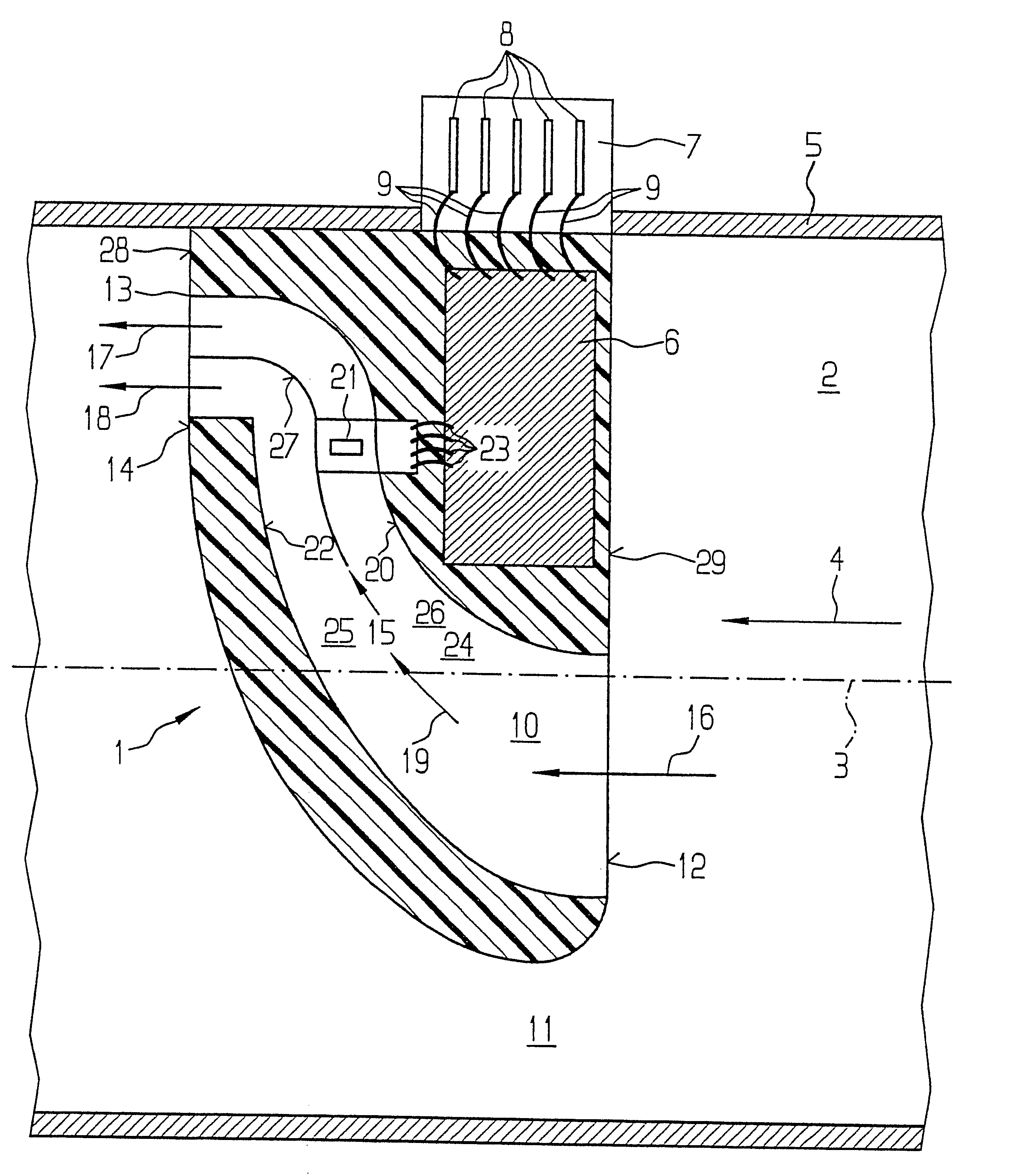
FIG. 1, in a sectional view, shows a side view of a measuring device 1 according to the invention, which is used to measure the mass of a flowing medium, in particular the aspirated air mass of internal combustion engines.

The measuring device 1 detects the mass of a medium flowing in a flow line 2. The flow line 2 is shown merely schematically and extends along a longitudinal axis 3, at least in the region of the measuring device 1. The flow line 2 may for instance be an intake line of an internal combustion engine, by way of which the engine can aspirate air from the environment. In the exemplary embodiments shown, the medium, such as the aspirated air, flows from right to left through the flow line 2. The flow direction in the flow line 2 is indicated by an arrow 4.

The measuring device 1 preferably has a slender shape extending radially in the flow line 2, and it can preferably be inserted, for instance in plug-in fashion, into an opening made in the wall 5 of the flow line 2. Emb...


PUM


Abstract

A measuring device for measuring the mass of a medium flowing in a flow line, in particular the aspirated air mass of an internal combustion engine, including a measuring element bathed by the flowing medium and disposed in a flow conduit of the measuring device provided in the flow line. The flow conduit extends in a primary flow direction between an inlet opening that communicates with the flow line and at least one outlet opening that discharges into the flow line downstream of the inlet opening. The flow conduit branches at a first dividing point, disposed between the inlet opening and the measuring element, into a measuring conduit, in which the measuring element is disposed, and a first bypass conduit, which bypasses the measuring element in the primary flow direction.

Description

PRIOR ARTThe invention is based on a measuring device for measuring the mass of a medium flowing in a line, also known as a flow rate meter. From German Patent DE 44 07209 C2, a measuring device is already known in which a flow conduit is integrated with a measuring module. The flow conduit receives the measuring element and tapers increasingly in the flow direction, beginning at an inlet opening. The tapered portion is adjoined by the S-shaped deflection conduit, which has a rectangular cross-sectional profile. The measuring module is embodied as a plug-in component. A substrate part of the measuring module can be inserted sealingly into the wall of the line to be measured and receives an electronic evaluation circuit.As the measuring element, a micromechanical component, of the kind known for instance from German Patent Disclosure DE 43 38 891 A1, is especially suitable. In the measuring element known from DE 43 38 891 A1, two temperature-sensitive resistors are integrated; they c...

Claims


Application Information

Patent Timeline
IPC IPC(8): G01F1/684G01F15/00G01F1/72G01F15/12G01F5/00
CPCG01F1/6842G01F1/72G01F5/00G01F15/12G01F1/684
Inventor HECHT, HANSMUELLER, WOLFGANG
Owner ROBERT BOSCH GMBH
Why Eureka
Try Eureka