
Fixing device for quickly fastening and releasing a mechanical part that bears on a support base

a technology of fixing device and mechanical part, which is applied in the direction of couplings, rod connections, ropes and cables for vehicles/pulleys, etc., can solve the problems of causing the head of the screw to rotate, and the rotation of the bayonet mechanism can be guaranteed. , to achieve the effect of quick and reliabl

Inactive Publication Date: 2002-01-08
SERAC GROUP
View PDF6 Cites 57 Cited by
  • Summary
  • Abstract
  • Description
  • Claims
  • Application Information

AI Technical Summary

Benefits of technology

An object of the invention is to design a fixing device both for fastening and for releasing, and which is both quick and reliable concerning latching and tightening during repeated fastening and release operations.
In addition, when the fixing device is for fitting to packaging installations or other installations concerned with foodstuffs, it is desired that the resulting fixing should be non-dirtying, i.e. free from any external portions presenting particles of pollution such as grease. Finally, to comply with the looked-for requirements of fastening and release operations taking place quickly, accessibility of the drive means and simplicity of the driving operations naturally constitute an object that is particularly desired for the preferred embodiment of the invention.
Also preferably, the ring and the drive member carry complementary means for rotary drive that act during unscrewing of said drive member. The release process can then take place in extremely simple manner without the need to use any kind of external tool.
It is also advantageous to provide for the ring to be constrained to rotate with the screw by indexed linking that allows relative movement along the direction of the axis of the screw.
In which case it is advantageous for the external profiles of the ring and of the drive member to be included within the profile of the cutout of the mechanical part to be fixed, thereby enabling said part to be put into place or extracted while it is in the corresponding angular position and without it being necessary to remove the drive member.

Problems solved by technology

That sequence of movements of the device relies exclusively on the relative values of the resistive forces acting on the screw-and-nut, and also on the female part and the studs, such that if the nut is not properly engaged in the female part, rotating the head of the screw can give rise to tightening even though latching has not been performed properly.
In addition, when untightening it is not possible to guarantee that the bayonet mechanism is caused to rotate.

Method used


Image

  • Fixing device for quickly fastening and releasing a mechanical part that bears on a support base
  • Fixing device for quickly fastening and releasing a mechanical part that bears on a support base
  • Fixing device for quickly fastening and releasing a mechanical part that bears on a support base

Examples


first embodiment

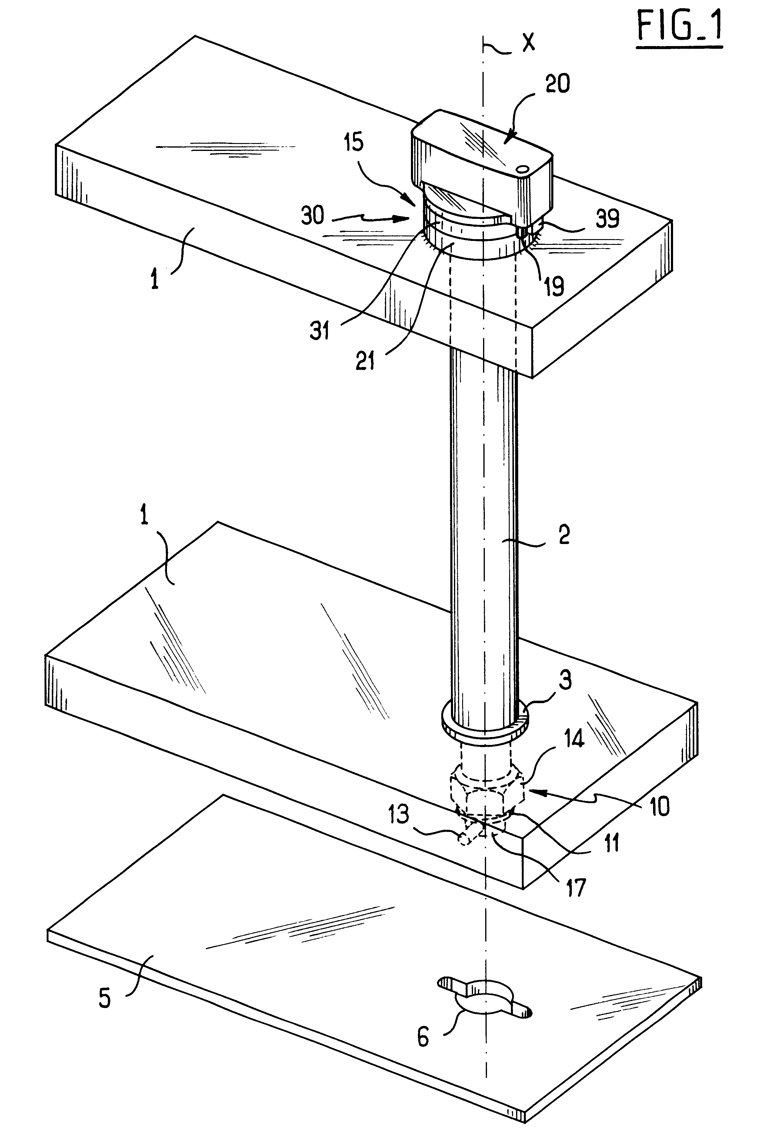
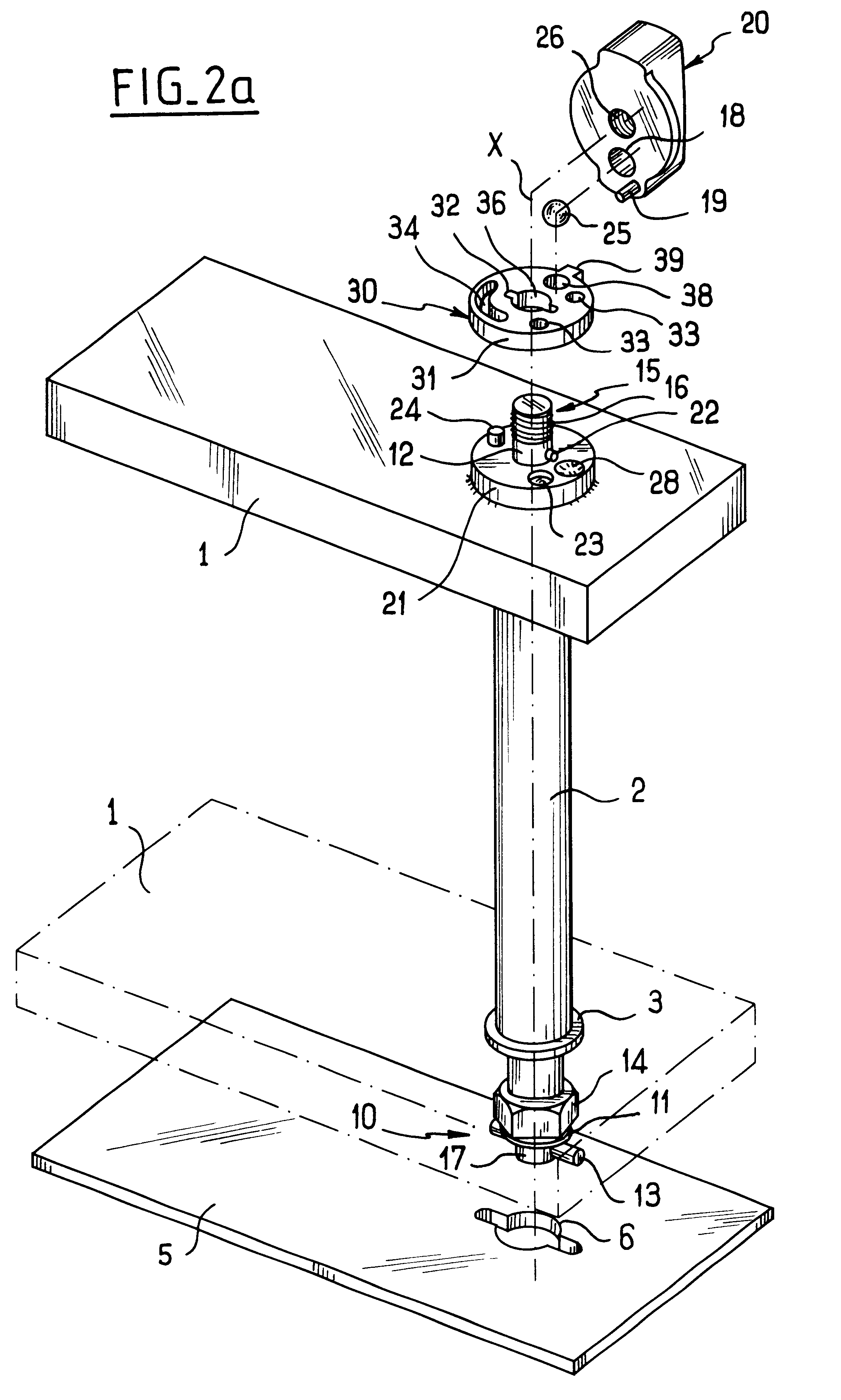
the invention is described below with reference to FIGS. 1 to 2c.

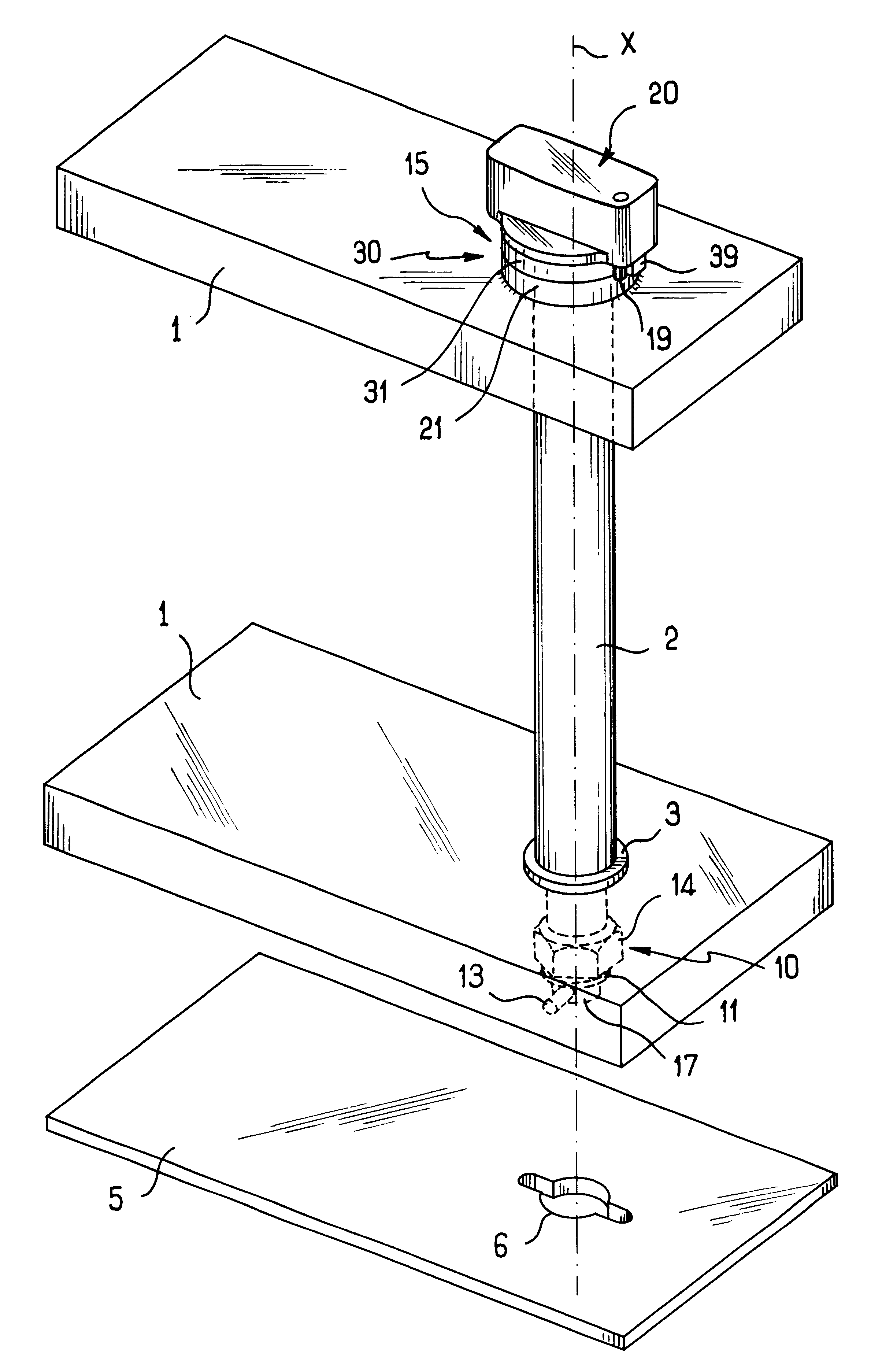
The mechanical part to be fixed is a piece of tooling, in this case constituted by two superposed bars 1, e.g. forming a set of two curved guide bars of the kind used in packaging installations, in particular installations for filling or stoppering receptacles, so as to keep the receptacles traveling around an associated star wheel or cylinder. In this case, the bars 1 are spaced apart by a hollow link tube 2 along which there pass various members used for fixing this tooling to a support base referenced 5.

The fixing device comprises firstly a latching mechanism 10 with some of the components thereof being visible in FIG. 1. The bottom bar 1 is held between a nut 14 and a bearing collar 3 that is rigidly secured to the hollow tube 2. Beyond the nut 14, there can be seen the free end 17 of a central rod that passes along the inside of the hollow tube 2, the rod having projecting portions that are implemented in this cas...


PUM


Abstract

The invention relates to a fixing device for quickly fastening and releasing a mechanical part that bears on a support base, the device comprising a latching mechanism of the bayonet type and an associated clamping mechanism of the screw-and-nut type that is organized coaxially therewith, the mechanisms being actuated one after the other by actuating a common rotary drive member in the same direction, and the device having a temporary coupling means interposed between that member and the mechanisms so that over a first angle of rotation of the drive member said drive member actuates the latching mechanism, and then over a second angle of rotation, said drive member is uncoupled from the latching mechanism and actuates the clamping mechanism.

Description

The present invention relates to a fixing device for quickly fastening and releasing a mechanical part that bears on a support base.Although the invention is not limited to any specific type of mechanical part for fixing to its support base, it relates more particularly to fixing tooling on an associated support base, which tooling needs to be put into place quickly and accurately on the support base, and then fixed thereto in reliable manner. Reference can be made in particular to the tooling fitted to packaging installations, in particular installations for filling or stoppering receptacles. The tooling in such installations conventionally comprises guide bars in the form of curved flat section members associated with star wheels or cylinders having curved notches or recesses serving to drive receptacles so that they are displaced along the conveyor line of the packaging installation.In existing installations, such tooling is fixed by releasable links of various types. Mention can...

Claims


Application Information

Patent Timeline
Patent Type & Authority Patents(United States)
IPC IPC(8): B65G47/84F16B21/04F16B21/00F16B1/02
CPCB65G47/846F16B21/04Y10T403/1616Y10T403/7007Y10T403/7005
Inventor DE VILLELE, DAMIEN
Owner SERAC GROUP
Learn More