
Electrical connecting device having mating state indication means

a technology of signaling means and connecting devices, which is applied in the direction of coupling device connection, coupling contact member, coupling device engaging/disengaging, etc., can solve the problems of late detection with many drawbacks, no solution to such an issue, and high cost and safety. achieve the effect of quick and reliable checking

Inactive Publication Date: 2010-12-21
FCI AUTOMOTIVE HLDG
View PDF8 Cites 18 Cited by
  • Summary
  • Abstract
  • Description
  • Claims
  • Application Information

AI Technical Summary

Benefits of technology

[0005]It is an object of the invention to provide an electrical connecting device, the full mating of which could be ensured at an early stage, by way of a quick and reliable checking operation.
[0007]Thanks to the invention, the full mating state of the connecting device can be easily checked as soon as both connector parts mate. The switching means provides the information on the mating state and the RFID tag allows collecting this information.

Problems solved by technology

Such a late detection has many drawbacks, in terms of cost and safety.
There is no solution to such an issue.

Method used


Image

  • Electrical connecting device having mating state indication means
  • Electrical connecting device having mating state indication means
  • Electrical connecting device having mating state indication means

Examples


Embodiment Construction

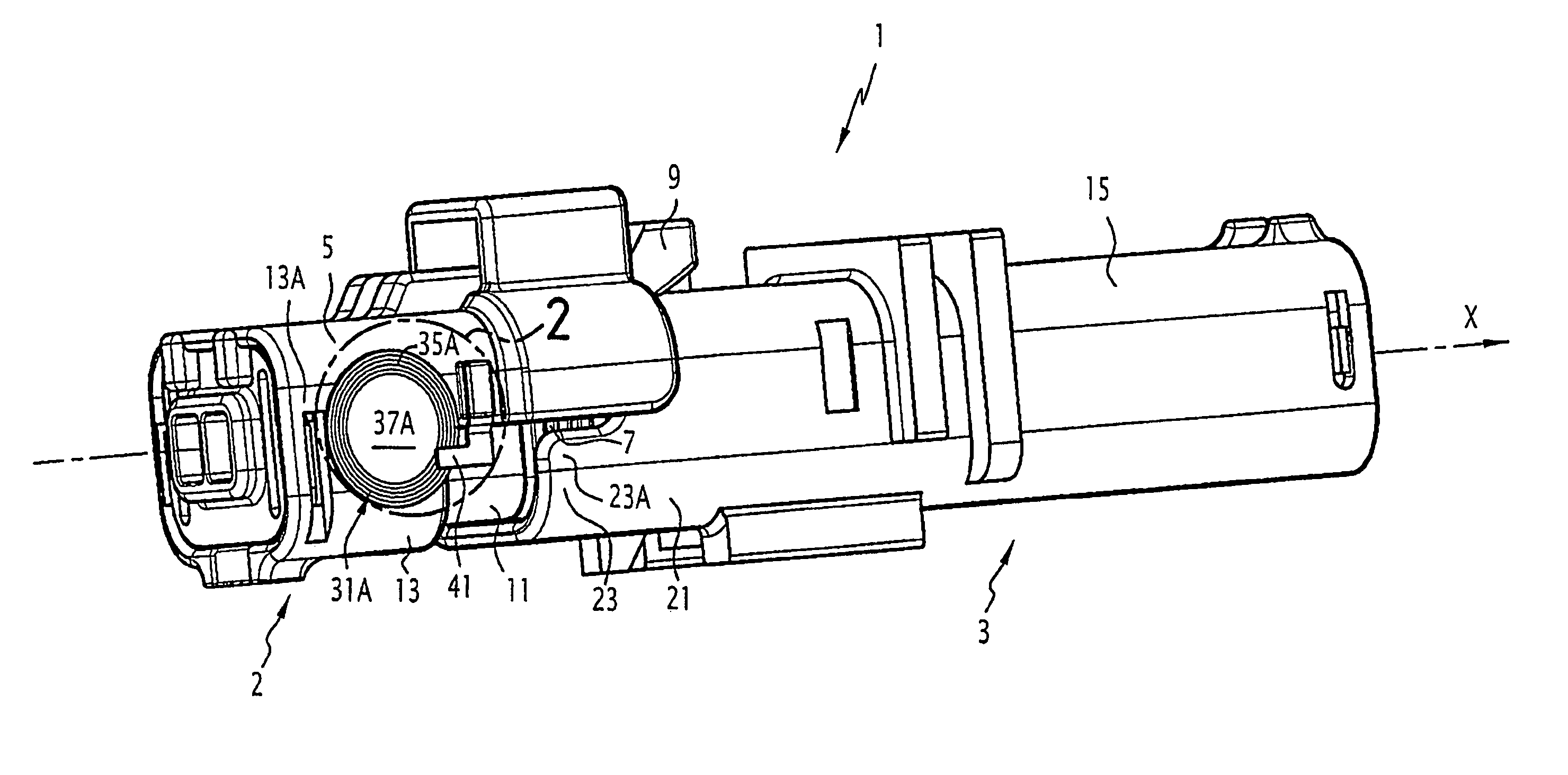
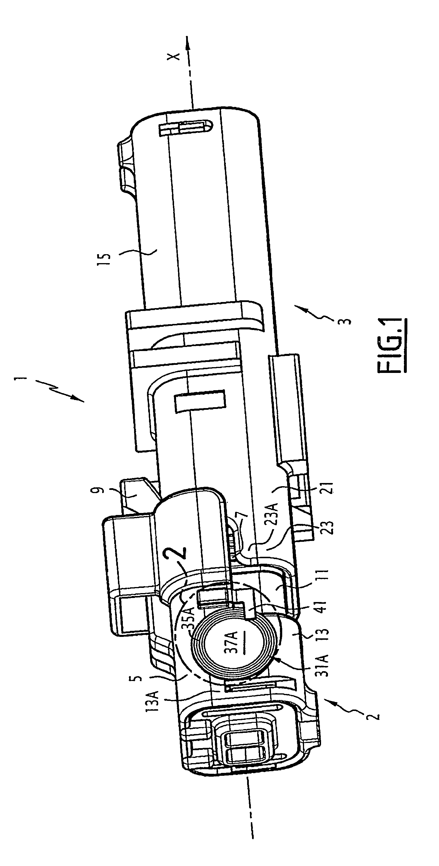
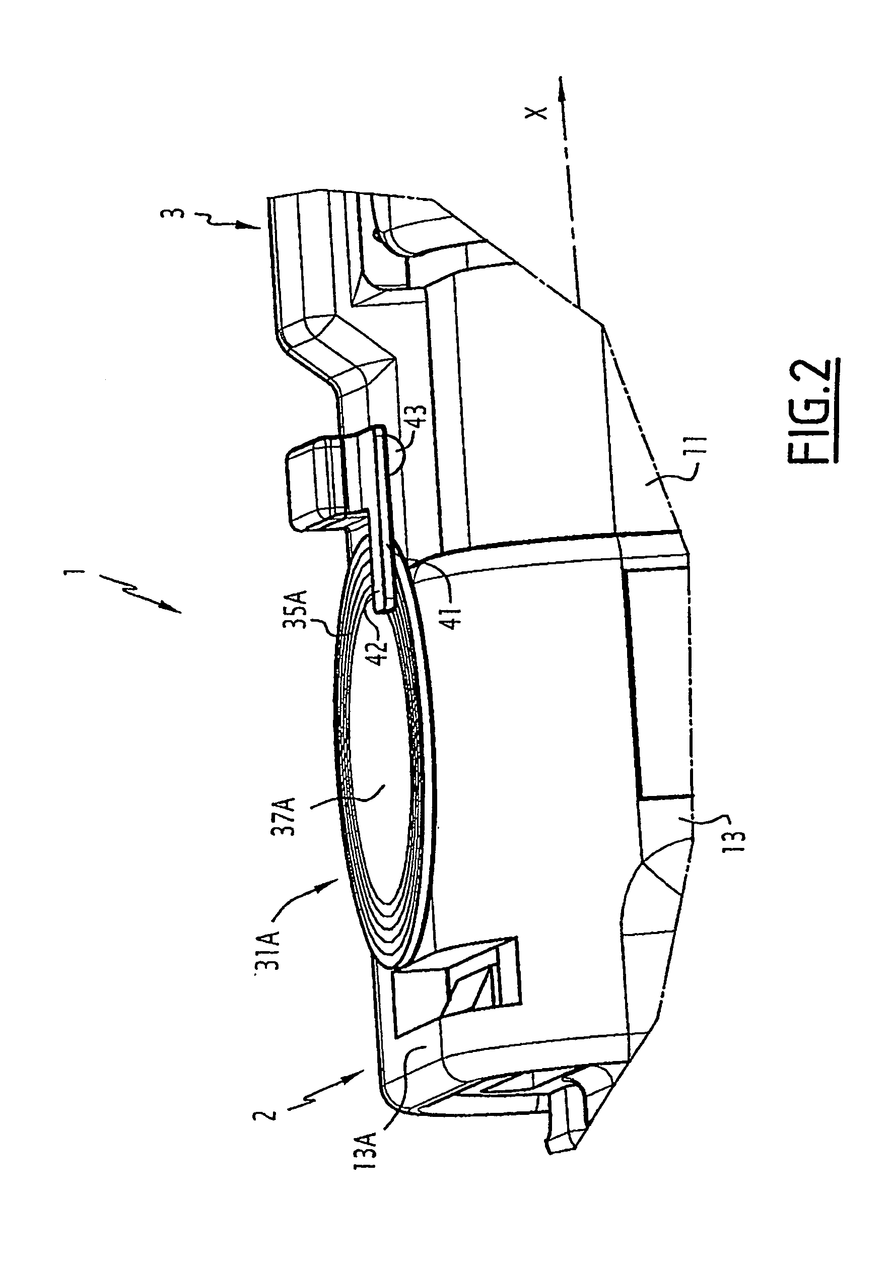
[0015]A connecting device 1 according to the invention is shown on the Figures.

[0016]In the example shown, the connecting device is a two-way connecting device of a type used in an automotive application.

[0017]It comprises two complementary connectors, that is a connector 2 and a counterpart connector 3, said connectors being suitable to mate.

[0018]On the Figures, the X-axis represents the mating direction attached to the connector 2, and is oriented from the connector 2 towards the counterpart connector 3 in mating conditions.

[0019]The orientation or position terms used in the present description and related to the connector 2, in particular the terms “forward” or “front”, refer to this mating axis X.

[0020]The connector 2 comprises an insulating housing 5, wherein a plurality of terminal accommodating chambers (not shown) are formed, a peripheral joint 7, and locking means 9, provided to releasably lock the connector 2 onto the counterpart connector 3.

[0021]The housing 5 has a gene...


PUM


Abstract

This connecting device has a connector and a counterpart connector suitable to mate therewith, and at least one RFID tag attached to one of said connectors and suitable to communicate with reader, said RFID tag including an antenna. The device further includes a switch adapted to put the RFID tag either in a first communication state or in a second communication state, depending on the full or incomplete mating state of the connectors.

Description

BACKGROUND OF THE INVENTION[0001]The invention relates to an electrical connecting devices and connectors. More particularly, the invention concerns electrical connecting devices for automotive vehicle.[0002]In the manufacturing process of automotive vehicles, an incomplete mating of connectors, which may occur during an assembling step, is usually detected through a specific checking operation at the end of the car making process, or even at a later stage, during the during the use of the car, after failure of the electrical equipment.[0003]Such a late detection has many drawbacks, in terms of cost and safety.[0004]There is no solution to such an issue.SUMMARY OF THE INVENTION[0005]It is an object of the invention to provide an electrical connecting device, the full mating of which could be ensured at an early stage, by way of a quick and reliable checking operation.[0006]Accordingly, the invention provides an electrical connecting according to claim 1.[0007]Thanks to the invention...

Claims


Application Information

Patent Timeline
Patent Type & Authority Patents(United States)
IPC IPC(8): H01R3/00
CPCH01R13/629H01R43/26
Inventor RADENNE, JEAN-PIERREREGNIER, FREDERICCASSES, CLAUDEGUILLANTON, ERWAN
Owner FCI AUTOMOTIVE HLDG
Learn More