Steering column for a steer-by-wire steering device

a technology of steering column and steering device, which is applied in the direction of steering parts, power driven steering, vehicle components, etc., can solve the problems of relative voluminous design, and achieve the effect of easy adjustment of axial direction friction, quick and reliable movement, and few tolerance fluctuations

Active Publication Date: 2018-11-08
THYSSENKRUPP PRESTA AG +1
View PDF4 Cites 22 Cited by
  • Summary
  • Abstract
  • Description
  • Claims
  • Application Information

AI Technical Summary

Benefits of technology

The invention is a steering column for vehicles that uses wireless technology to control the steering. The design of the column allows for a compact and easy-to-adjust feature. An actuator is included in the column to provide haptic feedback to the driver and improve safety while driving. Overall, the invention is a compact and adjustable steering column that is easy to install and provides improved driving experience.

Problems solved by technology

In this context, with previously known steering columns it is disadvantageous that the spindle drive is attached with an externally exposed threaded spindle to the casing unit.
This already results in a relatively voluminous design which is made even larger by protection devices for the threaded spindle, and is therefore only suitable for steer-by-wire steering systems to a limited degree.

Method used


Image

  • Steering column for a steer-by-wire steering device
  • Steering column for a steer-by-wire steering device
  • Steering column for a steer-by-wire steering device

Examples


first embodiment

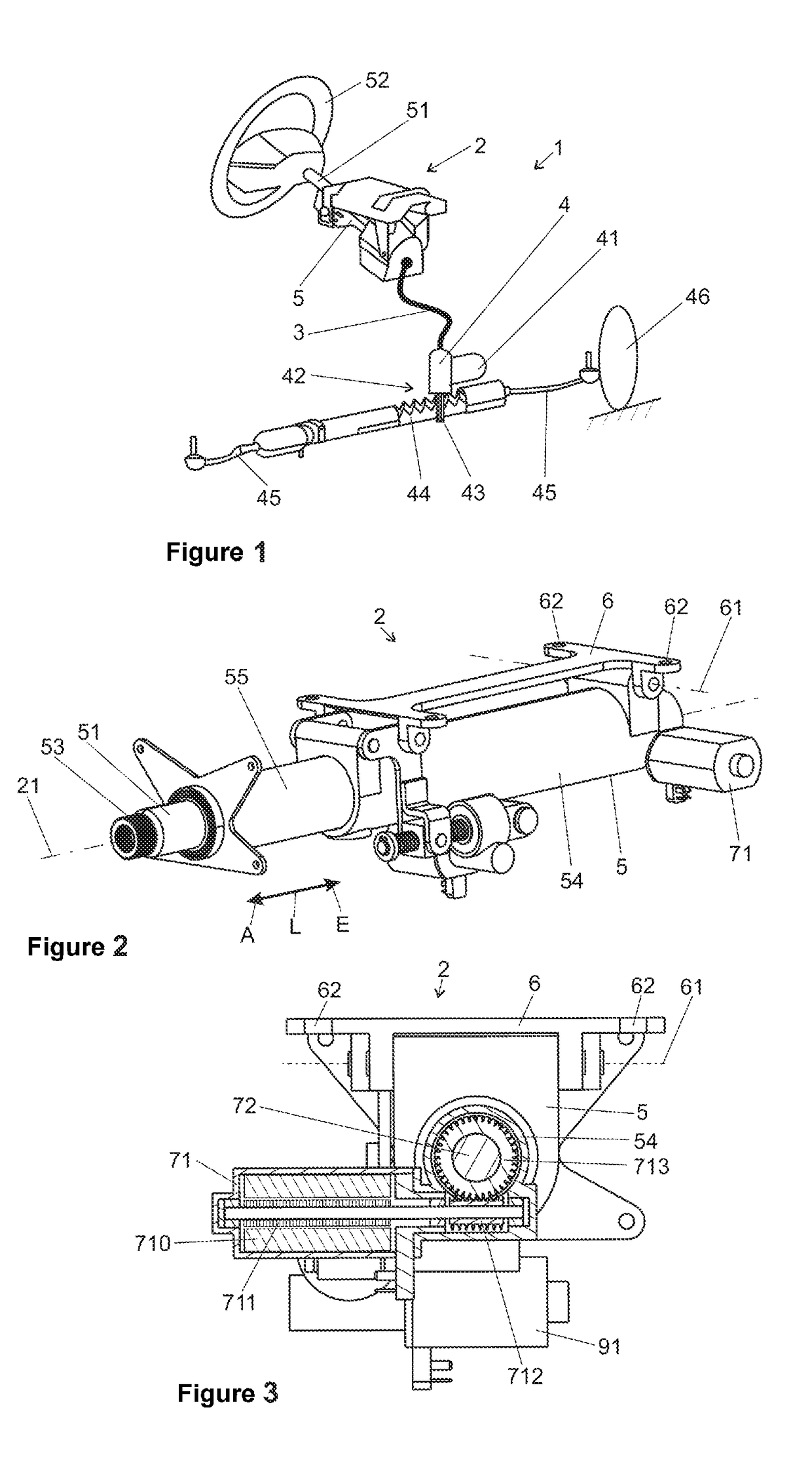
[0039]FIG. 2 shows the steering column 2 in a In the latter, the steering spindle 51 is mounted in the casing unit 5 so as to be rotatable about the longitudinal axis 21. The end section 53 of the steering spindle 51 is designed for the attachment of a steering wheel 52 which is omitted in this illustration.

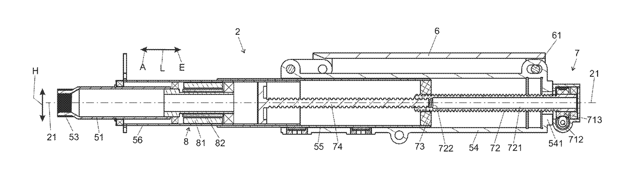
[0040]The casing unit 5 comprises a first casing tube 54, also referred to as an outer casing tube or boxed swing arm, in which a second casing tube 55, also referred to as an inner casing tube, is held coaxially. The inner cross section of the first casing tube 54 and the outer cross section of the second casing tube 55 are matched to one another in respect of shape and dimensions in such a way that the casing tube 55 can be moved axially in a telescopic fashion in the direction of the longitudinal axis 21 in the first casing tube 54, as indicated with the double arrow, in the longitudinal direction L forwards in the moving-in direction E and back in the moving-out direction A,...

second embodiment

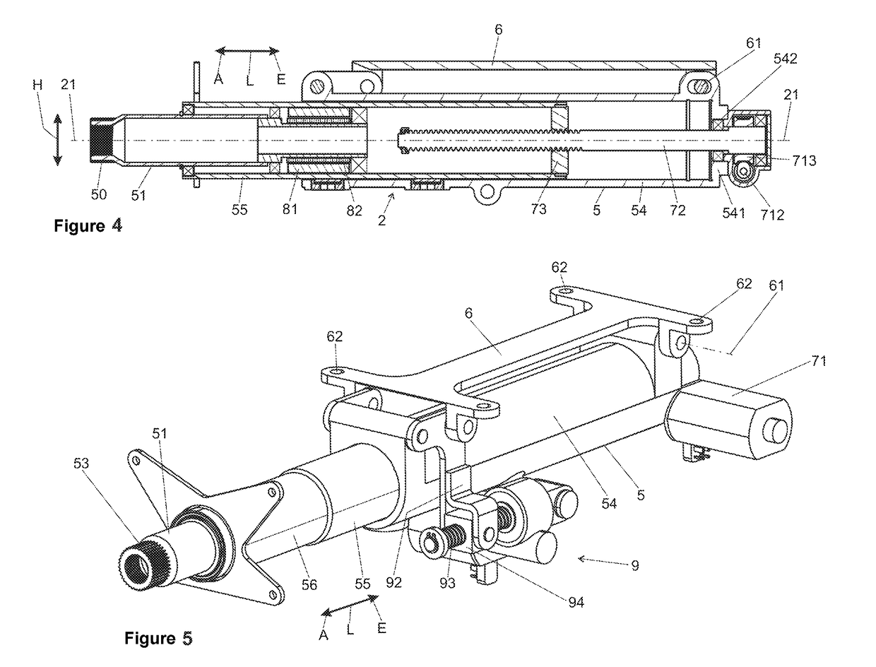
[0051]a steering column 2 according to the invention is illustrated in FIGS. 5, 6 and 7, wherein the same reference symbols are used for identical or identically acting parts. FIG. 5 shows a perspective view like FIG. 2, and FIGS. 6 and 7 show a longitudinal section as in FIG. 4, wherein FIG. 6 shows the steering column 2 in the moved-in state and FIG. 7 in the moved-out state.

[0052]In the second casing tube 55, a third casing tube 56 is arranged so as to be telescopic in the longitudinal direction L, specifically in principle in the way described above for the first casing tube 54 second casing tube 55. The casing tubes 54, 55 and 56 are secured against relative rotation with respect to the longitudinal axis, for example, by means of sliding guides (not illustrated), with the result that they cannot rotate with respect to one another when the threaded spindle 72 rotates.

[0053]A threaded bolt 74, which is arranged coaxially with respect to the longitudinal axis 21 and extends forwar...


PUM


Abstract

An adjustable steering column for a steer-by-wire steering device may include an actuating unit that comprises a steering spindle mounted rotatably about a longitudinal axis in a casing unit. The casing unit may have a first casing tube in which a second casing tube is arranged in a rotationally fixed manner with respect to the longitudinal axis and is mounted so as to be movable axially in a telescopic fashion. An actuating drive is connected to the first casing tube and the second casing tube and can move the second casing tube relative to the first casing tube. The actuating drive may comprise a spindle drive with a threaded spindle that is parallel to the longitudinal axis, rotatably drivable by a servomotor, supported on and extending within the first casing tube, and screwed into a spindle nut attached in a rotationally fixed manner to the second casing tube.

Description

PRIOR ART[0001]The invention relates to an adjustable steering column for a steer-by-wire steering device of a motor vehicle, comprising an actuating unit which comprises a steering spindle which is mounted so as to be rotatable about a longitudinal axis in a casing unit, wherein the casing unit has a first casing tube in which at least one second casing tube is arranged in a rotationally fixed fashion with respect to the longitudinal axis and is mounted so as to be movable axially in a telescopic fashion, wherein an actuating drive is connected to the first casing tube and the second casing tube, by which actuating drive the second casing tube can be moved in and out axially relative to the first casing tube, and which actuating drive comprises a spindle drive with a threaded spindle which is arranged parallel to the longitudinal axis, can be driven in rotation by an electric servomotor, is supported on a casing tube and is screwed into a spindle nut which is attached in a rotation...

Claims


Application Information

Patent Timeline
Patent Type & Authority Applications(United States)
IPC IPC(8): B62D1/181
CPCB62D1/181B62D5/008B62D6/008B62D5/001B62D1/183
Inventor KREUTZ, DANIELFORTE, SEBASTIAN
Owner THYSSENKRUPP PRESTA AG
Why Eureka
Try Eureka