Method of maintaining a superconducting cryolink at low temperature

Inactive Publication Date: 2002-01-29
NEXANS
View PDF8 Cites 23 Cited by
  • Summary
  • Abstract
  • Description
  • Claims
  • Application Information

AI Technical Summary

Benefits of technology

The aim of the invention is to overcome this drawback by proposing a method and a link architecture with sections having a length in the order of 100 km, or even several hundred kilometers, the investment and maintenance costs of which are low. To this end, the invention aims to

Problems solved by technology

The prior art architectures have the drawback of requirin

Method used


Image

  • Method of maintaining a superconducting cryolink at low temperature
  • Method of maintaining a superconducting cryolink at low temperature
  • Method of maintaining a superconducting cryolink at low temperature

Examples


Embodiment Construction

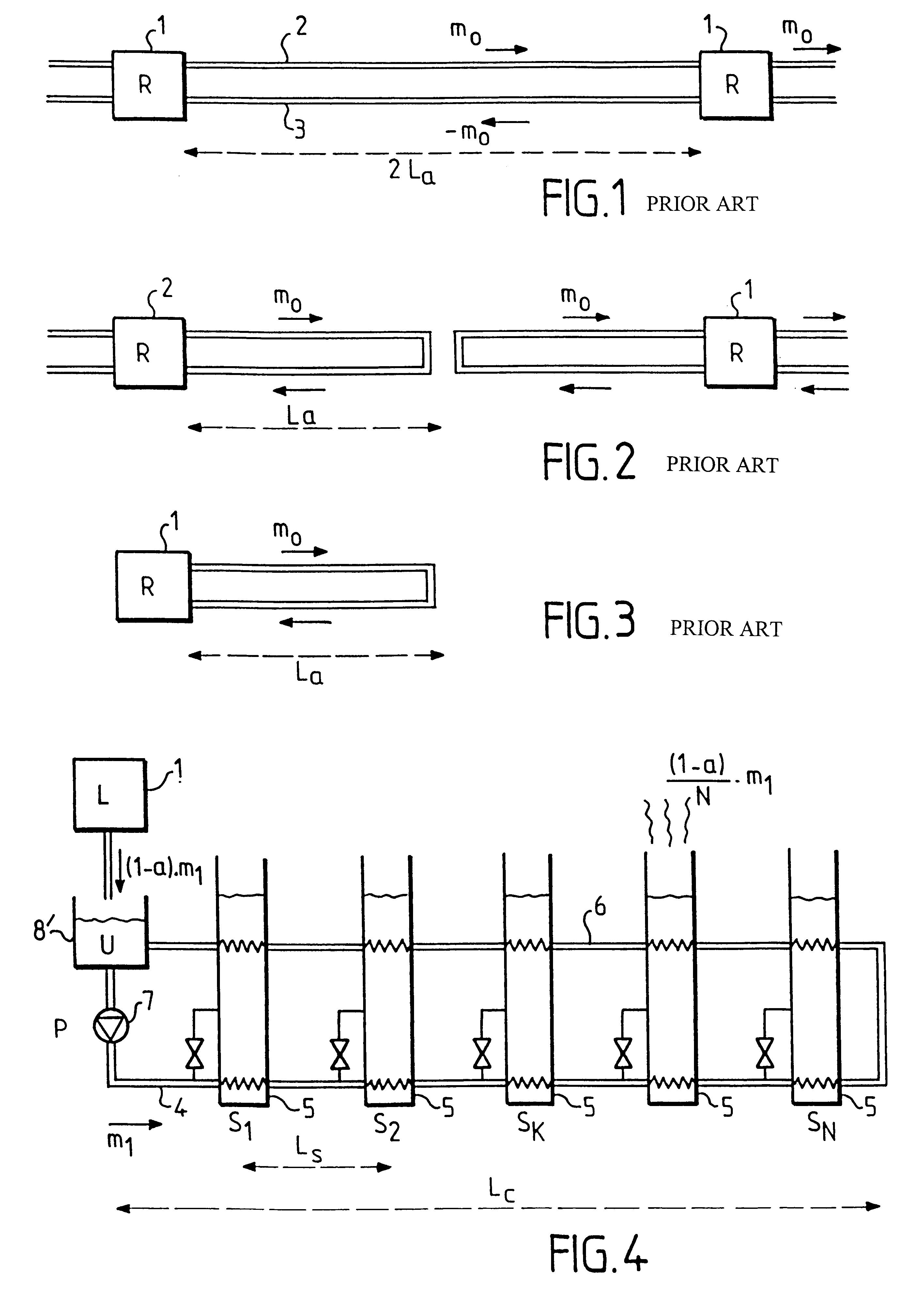
FIG. 4 is a diagrammatic view of a link half-section based on two parallel pipes (4, 6).

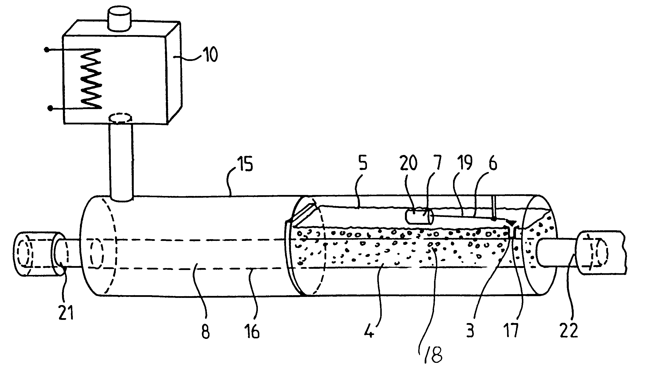
The pipe (4) is fed with liquid nitrogen by a liquefier (1) connected to a liquid nitrogen tank (8). The half-section has a length L.sub.c and is divided into N equal sectors of length L.sub.s. Between two consecutive sectors a small portion of the nitrogen flowing in the go pipe (4) is expanded to atmospheric pressure by a draw-off of station (5). The exchange of heat between the nitrogen bath obtained in this way at 77K and the go and return pipes (4) and (6) reduces the temperature of the two pipes (4, 6) and causes all of the nitrogen drawn off from the go pipe (4) to boil. Nothing is drawn off from the return pipe (6). The remaining nitrogen that has not been drawn off in the go pipe (4) decreases in flowrate from m.sub.1 to (a.m.sub.1) in the go pipe (4) by N step changes of the same value. The flowrate in the return pipe (6) remains equal to (a.m.sub.1)

The half-section also includes a circ...


PUM


Abstract

Method of maintaining a superconducting cryolink at low temperature by a flow of liquid nitrogen produced by a liquefier feeding one end of a link section, wherein the section is fed by a single liquefier and nitrogen is drawn off from at least one intermediate point of the link section.

Description

The present invention concerns the field of transporting electricity by means of a superconducting link.In the prior art, electricity is transported by a superconducting cable having superconducting link sections at a temperature which is held much lower than 90 K to maintain the superconducting state of the cable and to prevent the nitrogen from boiling.FIGS. 1 to 3 show the usual architecture of equipment for transporting current short distances by means of links cooled by liquid nitrogen. Prior art equipment of the above kind includes a set of liquid nitrogen refrigerators (1) arranged equidistantly along the installation. The same flowrate m.sub.0 of liquid nitrogen circulates in the go pipe (2) and in the opposite direction in the return pipe (3). The temperatures in the go and return pipes are 70K and 80K, for example.In the example shown in FIG. 1 two pipes (2, 3) which are thermally insulated from each other are of length 2L.sub.a, and the distance between two consecutive re...

Claims


Application Information

Patent Timeline
IPC IPC(8): H01B12/16
CPCH02G15/34Y10S505/885Y02E40/648Y10S505/886Y10S505/89Y10S505/889Y02E40/60
Inventor VERHAEGE, THIERRYHERRMANN, PETER FRIEDRICHMOISSON-FRANCKHAUSER, FRANCOIS
Owner NEXANS
Why Eureka
Try Eureka