
Loop antenna assembly

a technology of loop antenna and antenna assembly, which is applied in the field of loop antenna assembly, can solve the problems of difficult installation, difficult to assemble such a structure on the ground, and easy to be damaged or destroyed

Inactive Publication Date: 2002-01-29
PACKARD DANIEL A
View PDF7 Cites 31 Cited by
  • Summary
  • Abstract
  • Description
  • Claims
  • Application Information

AI Technical Summary

Problems solved by technology

Both the cubical quad and the delta quad antenna, however, display a number of disadvantageous characteristics.
First, due to the structural configuration of the antennae, they generally must be partially or completely assembled on the ground, making them quite difficult to install.
Obviously, it is very difficult to assemble such a structure on the ground and then mount it on a support structure.
Second, the geometries of the cubical quad and delta quad make the antennae mechanically unstable, leaving them quite susceptible to dammage or destruction due to adverse weather conditions, such as high winds and snow and ice loading, when made from materials commensurate with their sizes, and light enough in weight to avoid the necessity of an oversized support structure.
Consequently, as the operating frequency of the antenna drops too far below the resonant frequency of the driven element, the parasitic element will approach self-resonance, substantially deteriorating the performance of the antenna.

Method used


Image

  • Loop antenna assembly
  • Loop antenna assembly
  • Loop antenna assembly

Examples


Embodiment Construction

In the following detailed descriptions of the illustrative embodiments, for enhanced clarity, certain components, such as "U" bolts, saddle brackets, eyelets, unused draw lines, etc., will not be shown. For simplicity and clarity, certain components shown in more than one drawing will be designated with the same reference numerals.

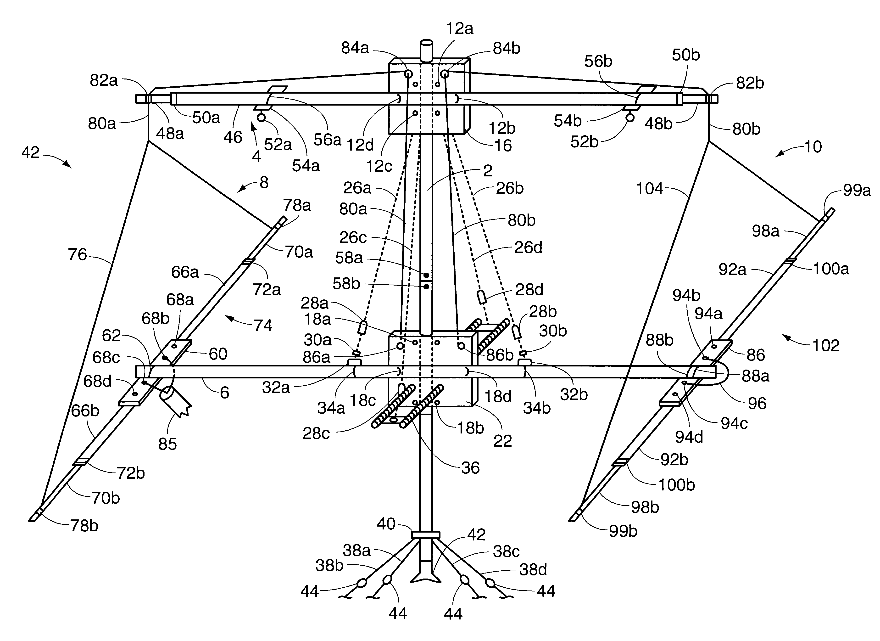
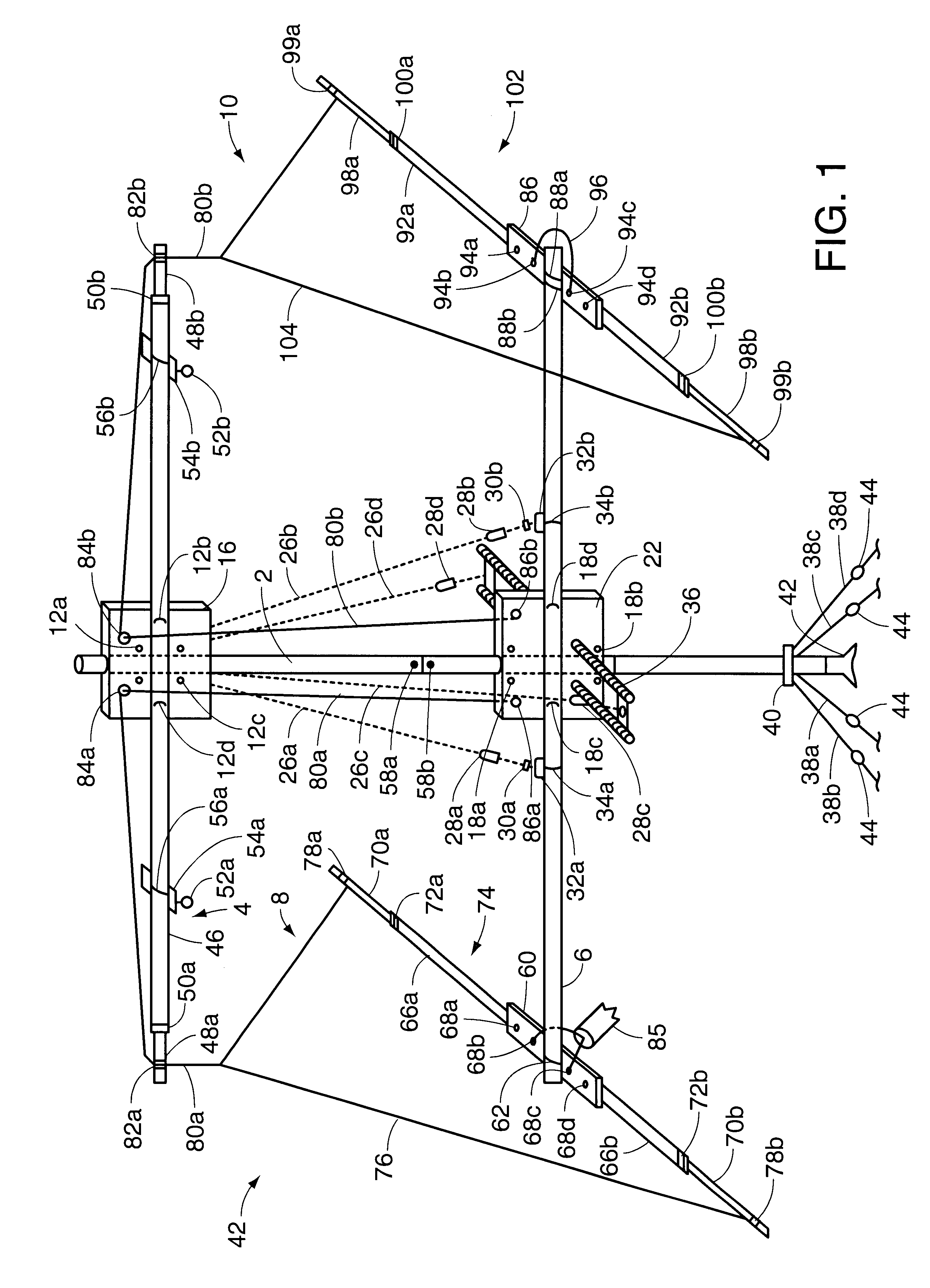
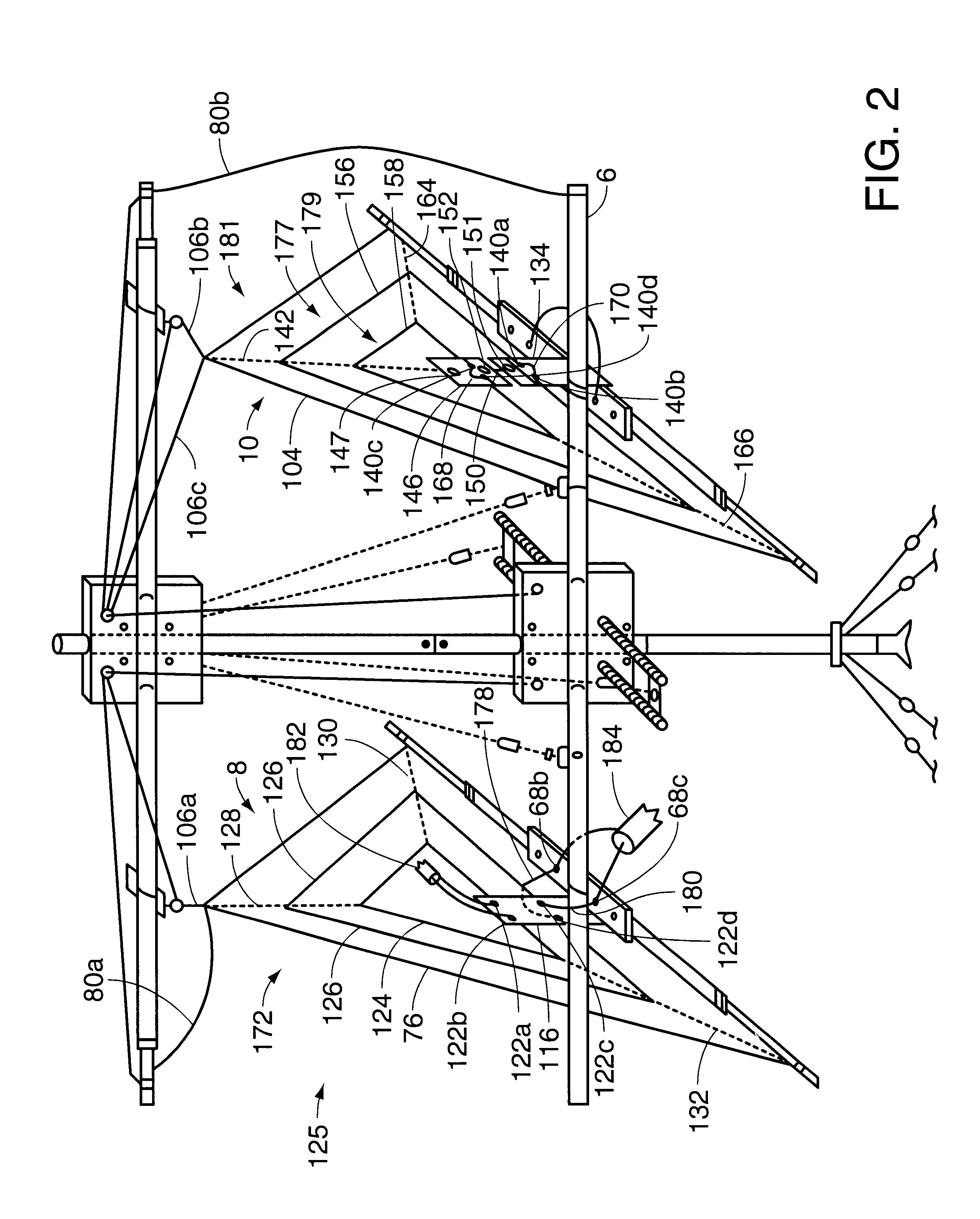
FIG. 1 shows a novel antenna assembly 42 which comprises a mast 2, a load-bearing upper boom 4, a lower boom 6, a triangular-shaped driven element 8, and a triangular-shaped parasitic element 10. The load-bearing upper boom 4 is attached to the mast 2 by means of four "U" bolts 12a, 12b, 12c, and 12d, and four saddle brackets (not shown), which are used to secure them to a metal plate 16. Similarly, the lower boom 6 is attached to the mast 2 by means of four "U" bolts 18a, 18b, 18c, and 18d, and four saddle brackets (not shown), used to secure them to a metal plate 22. The metal plate 16 contains four eyelets (not shown) to which four guy wires 26a, 26b, 2...


PUM


Abstract

A full-wave loop antenna assembly having unique mechanical stability and electromagnetic characteristics is disclosed. The antenna assembly is suitable for use in the High frequency and Very high frequency portions of the electromagnetic spectrum and is capable of supporting multiple driven and parasitic elements in a variety of configurations for multi-band operation. The assembly includes an upper load-bearing boom and a lower boom which may be load bearing, between which at least a part of the weight loads created by the driven and parasitic elements may be distributed. The assembly may also include a parasitic element, tuned as a reflector, which is considerably longer than other parasitic reflectors which are used with antennas of this type, thereby providing the desired directional characteristics over a wider range of frequencies than are obtained by other antennas of its type.

Description

1. Field of the InventionThis invention relates generally to the field of antennas, and more particularly to loop antenna assemblies intended for use in the high frequency and very high frequency portions of the electromagnetic spectrum.2. Discussion of the Prior ArtThe full wave loop antenna is generally recognized as one of the best conventional antennae for use in the high frequency and very high frequency portions of the electromagnetic spectrum for several reasons. First, the loop configuration tends to reduce fading on both transmission and reception. In addition, the full wave loop antenna provides enhanced directivity, gain, and "capture area" in comparison to other conventional antennae. Lastly, the full wave loop antenna is a "quiet" receiving antenna and displays a reduced level of "static" interference when compared with other conventional antennae.The two major types of full-wave loop antennae in wide use today in the high frequency and very high frequency spectrums are...

Claims


Application Information

Patent Timeline
Patent Type & Authority Patents(United States)
IPC IPC(8): H01Q3/02H01Q3/00H01Q3/12H01Q7/00H01Q1/14H01Q1/16
CPCH01Q1/16H01Q7/00H01Q3/12H01Q3/02
Inventor PACKARD, DANIEL A.
Owner PACKARD DANIEL A
Learn More