Display unit

a display unit and stereoscopic technology, applied in the field of stereoscopic images, can solve the problems of increasing the complexity and size of the whole formation

Inactive Publication Date: 2002-02-19
SEMICON ENERGY LAB CO LTD
View PDF15 Cites 27 Cited by
  • Summary
  • Abstract
  • Description
  • Claims
  • Application Information

AI Technical Summary

Problems solved by technology

However, such formations have had a problem that they require two images to be formed respectively by different image forming means, e.g. liquid crystal projectors, thus increasing the complexity and size of the whole formation.

Method used


Image

  • Display unit
  • Display unit
  • Display unit

Examples


first embodiment

[First Embodiment]

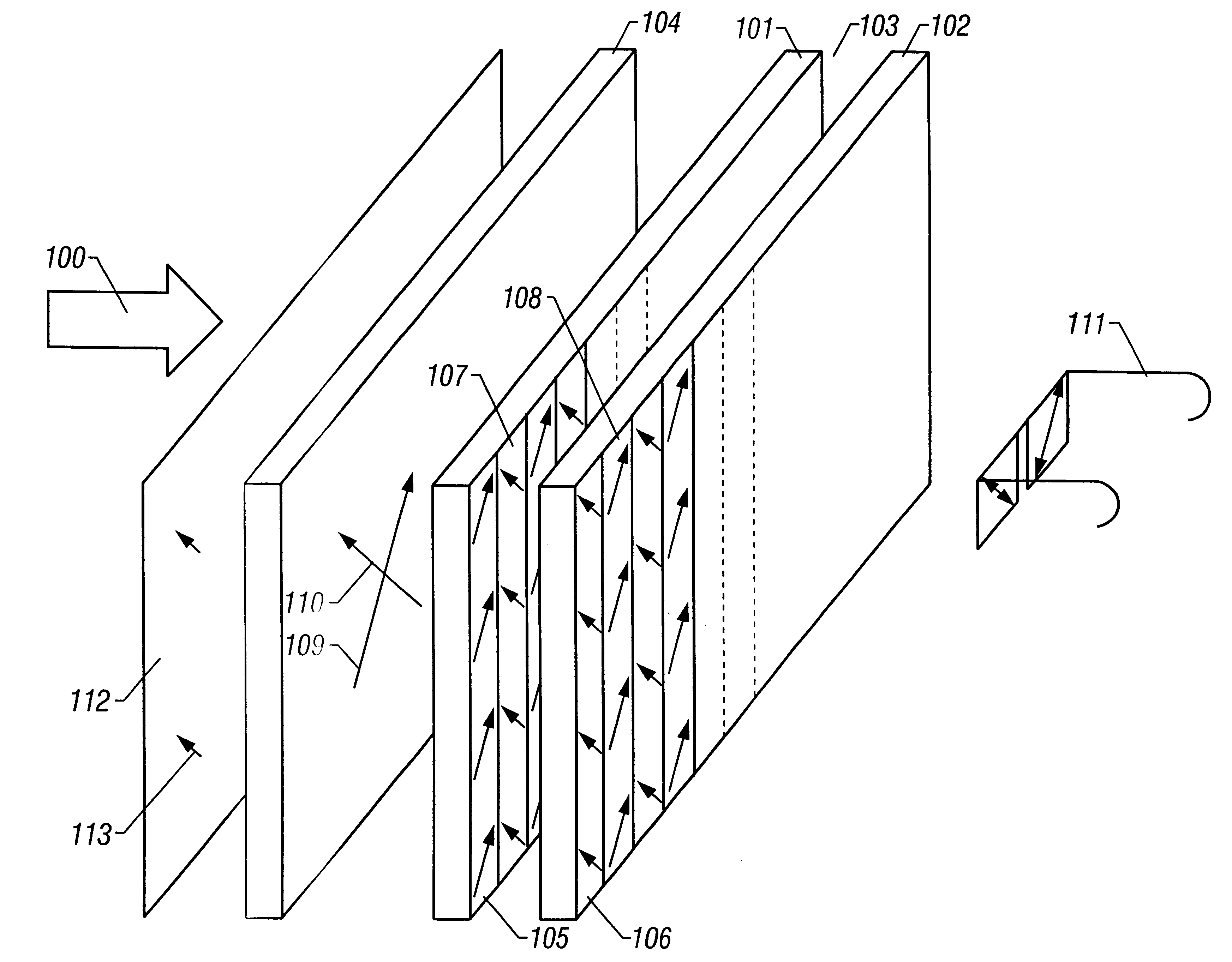
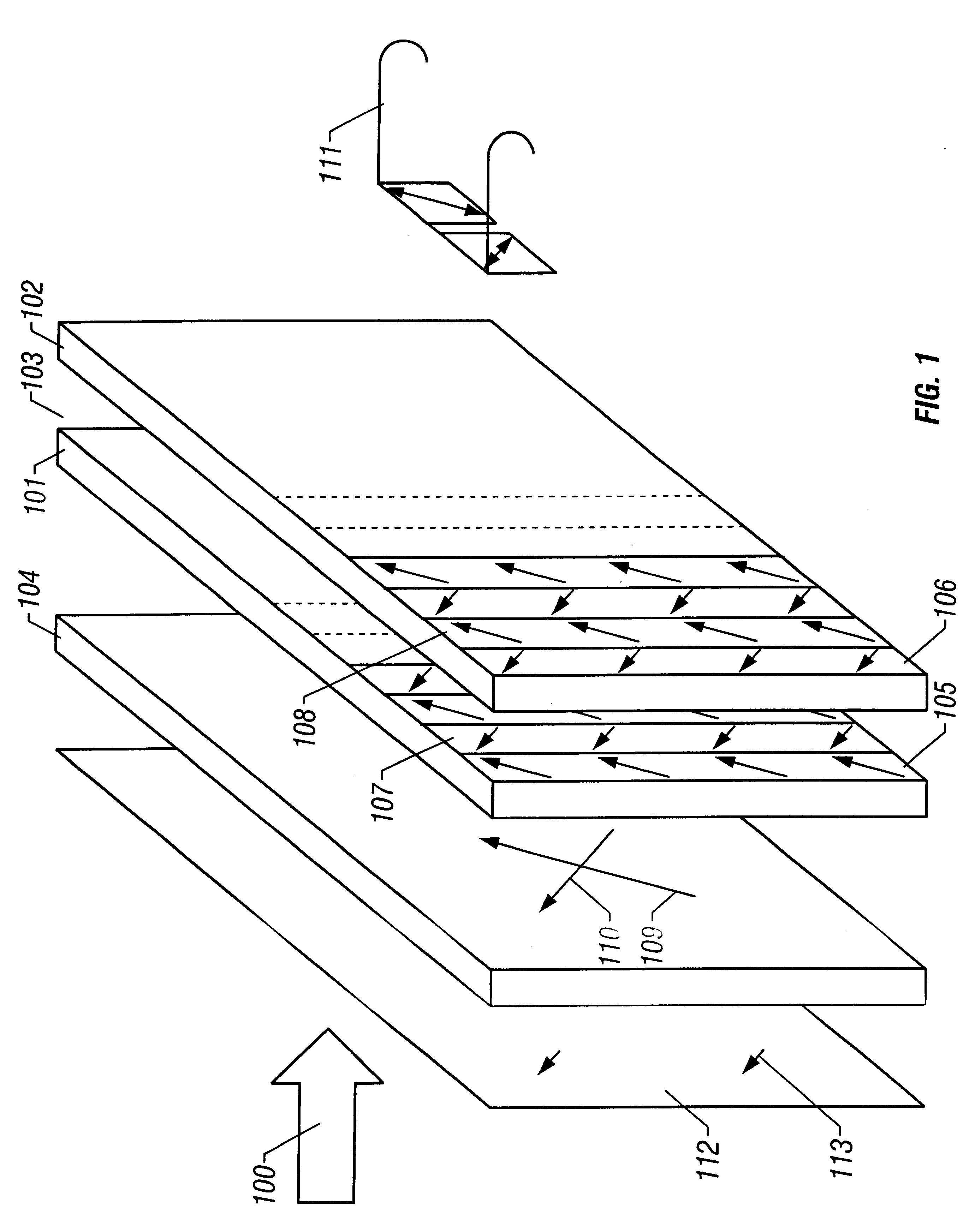
FIG. 1 shows a schematic formation of a direct-vision liquid crystal panel of one embodiment of the present invention. In the formation shown in the figure, white light 100 from a light source enters to a polarizing plate 112 at first. This polarizing plate has a polarizing direction indicated by an arrow 113. Accordingly, the light which has transmitted through the polarizing plate 112 becomes one which has been polarized linearly in the direction indicated by the arrow 113.

The light which has transmitted through the polarizing plate 112 enters to a .pi. cell 104. The .pi. cell is what utilizes TN type liquid crystal arid has a function of changing the polarizing direction by 90.degree.. Here, two linear polarization states indicated by arrows 109 and 110 can be selected by turning ON / OFF the .pi. cell 104.

Here, the .pi. cell is set so that light having the polarization indicated by the arrow 109 transmits through the .pi. cell when the .pi. cell is ON and light h...

second embodiment

[Second Embodiment]

The present embodiment relates to a formation of a display unit for providing different images to two observers, respectively. FIG. 3 shows the schematic formation of the present embodiment.

The formation of the display unit is the same with that shown in FIG. 1. Accordingly, the formation shown in FIG. 1 may be utilized as it is for the formation of the present embodiment.

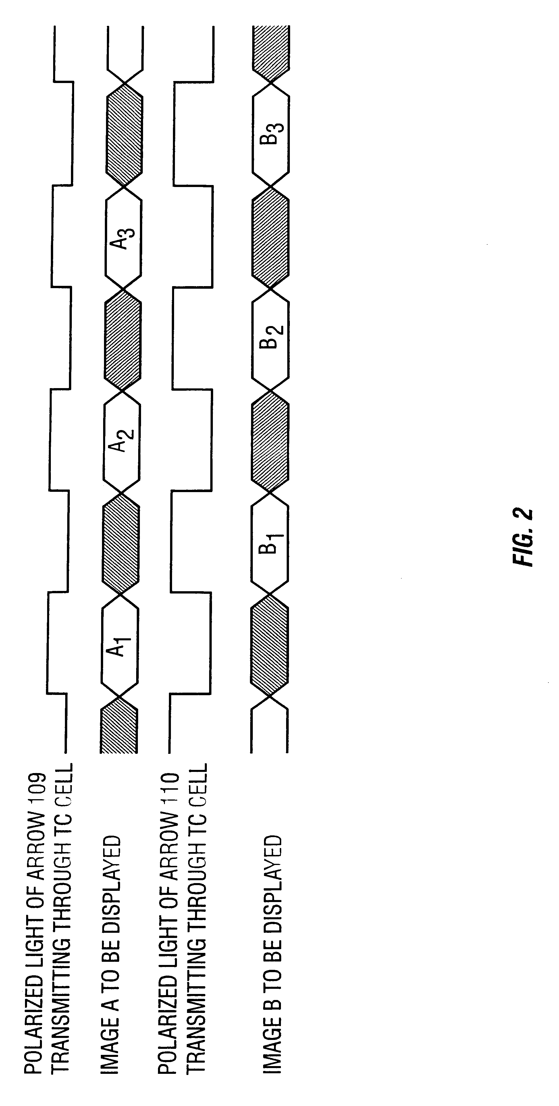
In the formation shown in FIG. 3, the observers view the display unit with glasses 301 and 302 on, respectively. Consider here that the images A and B shown in FIG. 2 are different from each other. Then, it becomes possible to create a state in which the observer with the glasses 301 on can see the image B and the observer with the glasses 302 on can see the image A, respectively.

third embodiment

[Third Embodiment]

The present embodiment relates to a formation of a display unit in which a quarter wavelength plate is disposed further on the display side of the substrate 102. Such formation can change the images A and B in FIG. 2 into circularly polarized lights whose turning directions are different from each other.

In this case, preferably, filters for selectively transmitting the right turn circularly polarized light and the left turn circularly polarized light are disposed on the part of the glasses 111 or 301 and 302 in the formation shown in the first embodiment or second embodiment.


PUM

PropertyMeasurementUnit
angleaaaaaaaaaa
timeaaaaaaaaaa
sizeaaaaaaaaaa

Abstract

A display unit which allows stereoscopic images to be displayed on a direct-vision liquid crystal panel is provided. The display unit has the formation in which liquid crystal is sandwiched in a gap between a pair of glass substrates. When linearly polarized lights whose polarizing directions are differentiated by 90° from each other by a pi cell are input alternately to the liquid crystal, images to be displayed turn out as two images whose polarizing directions differ by 90° from each other and which are displayed in a time-division manner. The images may be perceived as a stereoscopic image by viewing them by glasses having polarizing directions different by 90° for right and left eyes.

Description

The present invention relates to the formation of a direct-vision type liquid crystal display unit.Description of Related ArtAs a method for displaying stereoscopic images, a technology of supplying images specifically to right and left eyes has been known since the past ("Basics of Three-Dimensional Pictures" edited by NHK Science and Technical Research Laboratories under the supervision of Takehiro Izumi, Published by Ohm Sha, Ltd.).In concrete, there have been known a method of projecting an image for right eye and that for left eye by superposing each other on the same screen by using two projectors and of viewing them separately by right and left eyes by using special filters, and a formation adapted to enable to view different images by right and left eyes by using lenticular lenses.However, such formations have had a problem that they require two images to be formed respectively by different image forming means, e.g. liquid crystal projectors, thus increasing the complexity a...

Claims


Application Information

Patent Timeline
Patent Type & Authority Patents(United States)
IPC IPC(8): G02F1/1335G02F1/13G02F1/1337H04N13/00G02B27/22G03C9/08
CPCG02F1/133528G02F1/133753H04N13/0438H04N13/0434H04N13/0048H04N13/161H04N13/337H04N13/341
Inventor YAMAZAKI, SHUNPEIHIRAKATA, YOSHIHARUTERAMOTO, SATOSHIKOYAMA, JUN
Owner SEMICON ENERGY LAB CO LTD
Why Eureka
Try Eureka