Spin valve device with improved thermal stability

a technology of thermal stability and spin valve, which is applied in the field of spin valve sensor, can solve the problems of affecting the operation of the spin valve, the magnetization of the pinned layer to weaken, or change, and the current sensing effect itself creates undesirable effects within the spin valv

Inactive Publication Date: 2002-02-26
WESTERN DIGITAL TECH INC
View PDF13 Cites 181 Cited by
  • Summary
  • Abstract
  • Description
  • Claims
  • Application Information

AI Technical Summary

Problems solved by technology

The sensing current, does itself create undesirable effects within the spin valve.
The heat can cause the instability and noise within the sensor.
If the temperature of the sensor rises above the blocking temperature of the pinning layer, the pinning layer is no longer able to pin the magnetization of the pinned layer and may have its exchange coupling altered, causing the magnetization of the pinned layer to weaken, or change.
Turning to FIG. 1, another problem encountered with spin valves is Barkhausen noise.
This current induced magnetic field further reduces the strength of the pinned field and further contributes to Barkhausen noise.
Moreover, this field can change the orientation of the pinned layer if the temperature of the pinned layer rises above its blocking temperature, thereby causing permanent damage to the spin valve.
Although the magnitude, or direction, of the current through the spin valve may be changed to improve the magnetization characteristic of the pinned layer and to reduce Barkenhausen noise, it would also undesirably change the operating point of the spin valve and lead to asymmetrical output.

Method used


Image

  • Spin valve device with improved thermal stability
  • Spin valve device with improved thermal stability
  • Spin valve device with improved thermal stability

Examples


Embodiment Construction

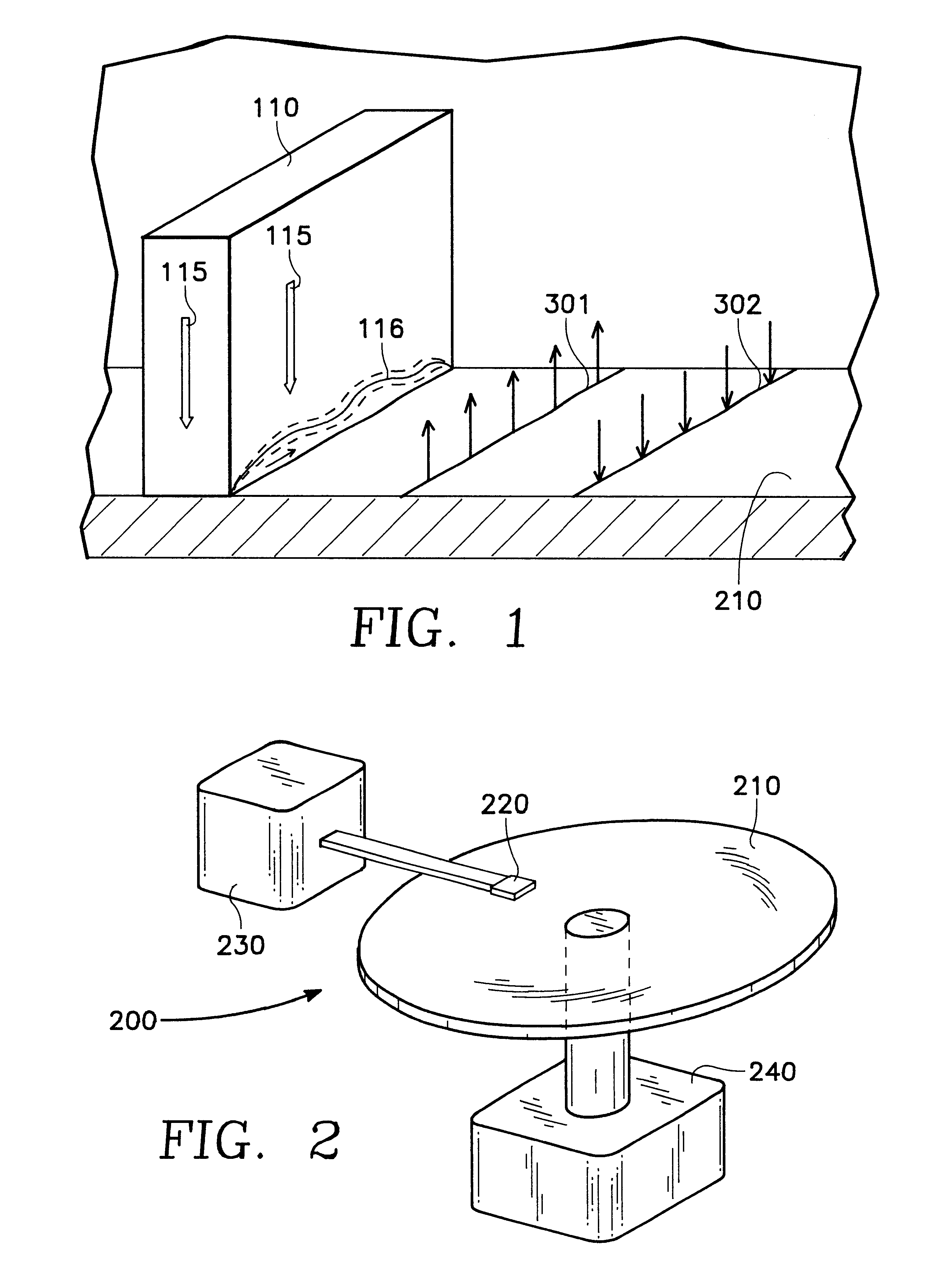
FIG. 2 shows the improved spin valve sensor of the present invention embodied in a disk type magnetic data storage and retrieval apparatus 200. The improved spin valve of the present invention may be located within a merged head assembly 220 which rides above a magnetic storage media 210, depicted in FIG. 2 as a rotatable hard disk type storage media. The hard disk is coupled to a motor 240 to provide rotation of the disk relative to the head assembly 220. An actuating means 230 may be used to position the head assembly 220 above the surface of the media 210 to read and write data in the form of magnetic bits from and to the media 210. The data storage and retrieval apparatus 200, typically has several hard disks 210 and several corresponding head assemblies 220.

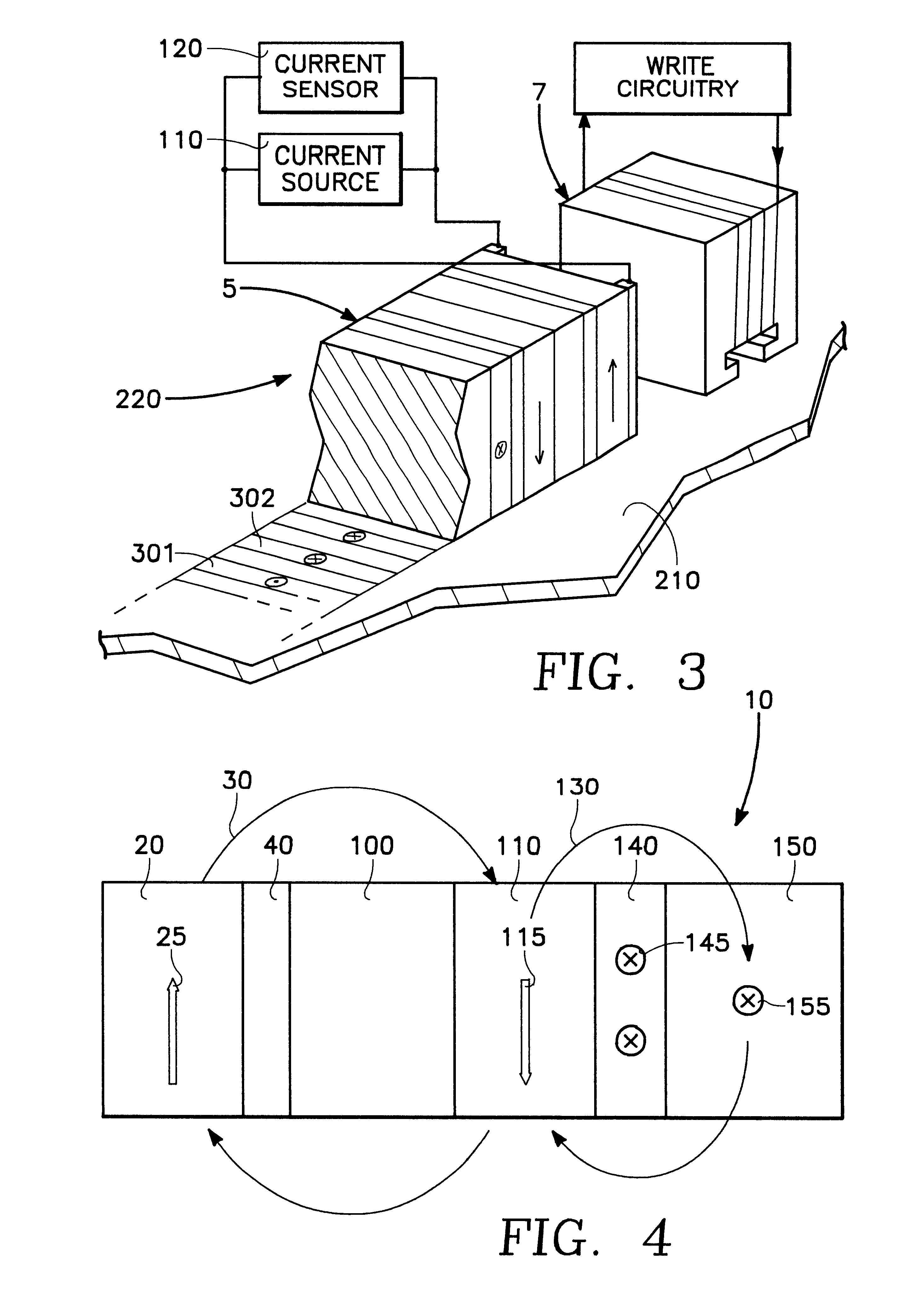
FIG. 3 shows a simplified functional illustration of the head assembly 220. Merged head assemblies 220 are formed having a write head 7, used to write or set the magnetization of bits 301, 302 on the media 210, while a read ...


PUM

PropertyMeasurementUnit
magnetic fieldaaaaaaaaaa
ferromagneticaaaaaaaaaa
magnetic compensation fieldaaaaaaaaaa

Abstract

The present invention provides spin valve with a magnetic compensation field which couples to the pinned layer and counteracts sensing current induced magnetic field. The spin valve sensor of the present invention may be formed having a structure comprising: a free layer, a first spacer layer, a pinned layer, a pinning layer, a second spacer layer, and a compensation layer. The compensation layer may be formed of ferromagnetic material with its magnetization set so that the compensation field oriented in a reinforcing relationship with the magnetization of the pinned layer. Current through the compensation layer and the spacer layer may add to the compensation field. The spacer layer may be formed of a nonmagnetic material of sufficient thickness to prevent interaction between the pinning layer and the compensation layer while providing a sufficiently small distance to allow sufficient magnetic coupling to the pinned layer. The present invention may be used to improve thermal stability and reduce Barkhausen noise while not impacting output symmetry.

Description

1. Field of the InventionThe present invention relates to the field of spin valve sensors.2. Background ArtSpin valve sensors exploit changes in electrical resistance which occurs as a result of manipulating the relative orientation of the magnetization of ferromagnetic layers within a spin valve sensor. In conventional spin valve sensors, one ferromagnetic layer has its magnetization pinned while another, which has its magnetization set perpendicular to the pinned layer, is free to change its magnetic orientation in response to magnetized bits on an adjacent recording media. The magnetized bits on the recoding media, therefore, change the relative magnetization direction of the free layer with respect to the pinned layer. A current through the spin valve is used to detect changes in the resistance of the spin valve that results from changes in the relative magnetization of the free layer. Typically, the magnetic field of the free layer is set perpendicular to the magnetization of i...

Claims


Application Information

Patent Timeline
Patent Type & Authority Patents(United States)
IPC IPC(8): G01R33/06G01R33/09G11B5/00G11B5/39G11B5/31
CPCB82Y10/00B82Y25/00G01R33/093G11B5/3903G11B5/00G11B2005/3996G11B5/3143
Inventor MIN, TAITONG, HUA-CHINGHUAI, YIMINGCHEN, WENGIE
Owner WESTERN DIGITAL TECH INC
Why Eureka
Try Eureka