

Feeding a needling machine with a continuous spiral strip
- Summary
- Abstract
- Description
- Claims
- Application Information
AI Technical Summary
Benefits of technology
Problems solved by technology
Method used
Image

Examples
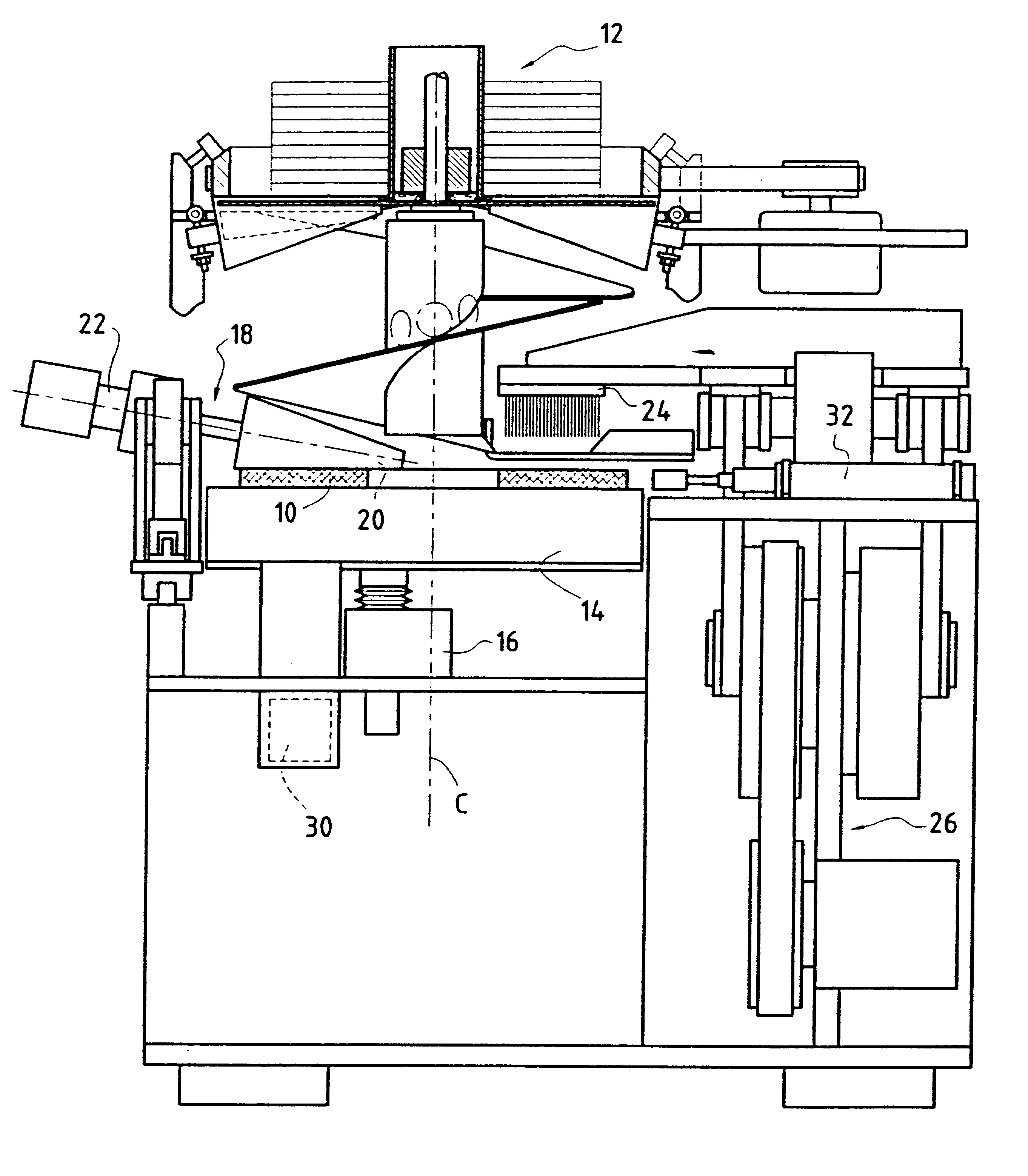
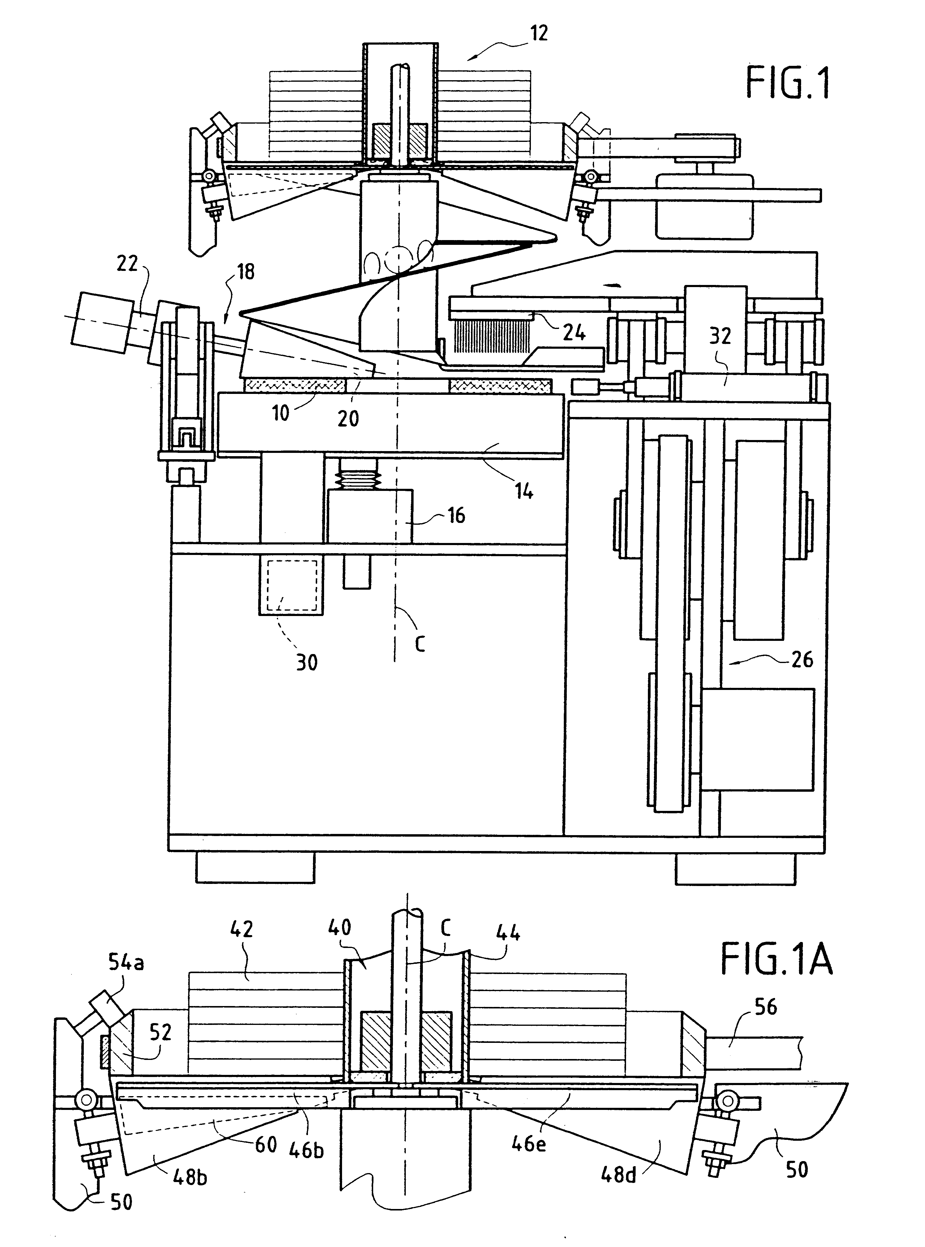
first embodiment
The path followed by the strip unwound along the helical chute from being extracted from the bottom of the drum until it is deposited on the needling table is shown in FIG. 5 which shows means for driving it.
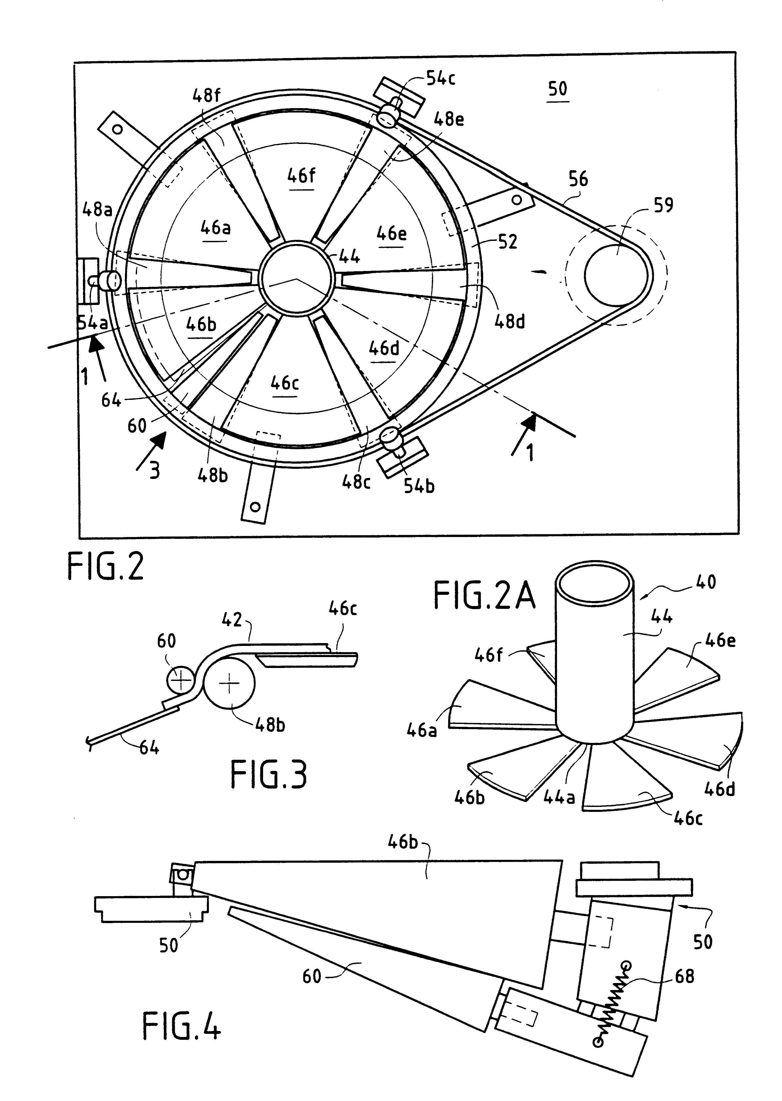
The helical chute secured to the frame 50 on the machine comprises two successive portions 64 and 66 which are separated solely by a gap 68 forming a slot to receive the cutting means 28. All along this path, the strip is kept in contact with the chute by drive means which are preferably combined into two separate assemblies 70 and 72 located respectively one (70) upstream from the cutting means 28 and the other (72) downstream therefrom. Each drive assembly is preferably driven by an individual motor and gear box unit 78, 80 controlled by the central control means 30. Nevertheless, it is equally possible to envisage using common motor means for both of them.
Each drive assembly 70, 72 has at least two and preferably three wheels 74a, 74b, 74c; 76a, 76b, 76c mounted on a respecti...
second embodiment
FIGS. 6A and 6B show separate drive assemblies 70, 72 in which, in order to fit more closely to the shape of the twist 64, the drive belt 82, 84 is mounted on a plurality of sloping wheels 92a, 92b, 92c, 92d, 92e, 92f. Two upright end wheels 94 and 96 and the same plurality of horizontal wheels 98a, 98b, 98c, 98d, 98e, 98f enable the belt to return, with one of the two upright wheels being connected to a motor and gear box unit 78, 80 by means of a universal joint 86, 88. It should be observed that the wheels can be hinged so as to enable them to be moved relative to the median axis of the twist so as to enable the textile sheet to be recentered, should that be necessary.
Another embodiment of these drive assemblies is shown in FIGS. 7A and 7B. With this new assembly, the textile material is driven by a plurality of wheels 100a, 100b, 100c, 100d independently hinged to the frame 50 (each subjected to the action of a resilient element 102) and the wheels are caused to rotate via respe...
PUM
| Property | Measurement | Unit |
|---|---|---|
| Tension | aaaaa | aaaaa |
| Friction | aaaaa | aaaaa |
Abstract
Description
Claims
Application Information