Weighing, packaging and inspecting system

a technology of weighing and packaging, applied in the direction of weighing apparatus details, weighing auxiliary devices, instruments, etc., can solve the problems of inability to grasp the deficiency of the production line, inefficient and expensive maintenance operation, and similar deficiency in successive processing of products

Inactive Publication Date: 2002-04-16
ISHIDA CO LTD
View PDF15 Cites 43 Cited by
  • Summary
  • Abstract
  • Description
  • Claims
  • Application Information

AI Technical Summary

Problems solved by technology

Once this unusual or abnormal event occurs, the weight of the articles M can no longer be measured accurately, resulting a weighing failure.
On the other hand, since the weighing hoppers 6i employed are in a plural number, much labor and time are required to find out one or more of the weighing hoppers 6i that have resulted in the weighing failure, resulting in inefficient and expensive maintenance operation.
In such system, since a plurality of machines are lined to perform in unison a series of processing to eventually produce the bagged product, it is difficult to grasp where deficiency has occurred in the production line once a defective product (NG product) is found.
In addition, once the defective product is found, a similar defect would occur in successively processed products.
However, according to the above discussed publication, there is a problem in that unless the operator makes a decision based on the displayed pieces of information associated with the respective processing machines, none of the processing machines can be determined having a deficiency.
Another problem also arise in that the nature of the deficiency in the processing machines ever found can not be easily determined and, for this reason, the decision making takes a substantial length of time, accompanied by reduction in productivity and production yield.
Since the weighing heads selected in the combination are different for a combination discharge, failure of one of the weighing heads to operate properly results in random occurrence of proper and improper combination calculated weights.
While the weight checker performs the well-known zero-point adjustment while no product exist on the conveyor, no zero-point adjustment can be performed if the number of items to be handled for unitary time is too many and, for this reason, the zero-point itself displace, resulting in a defective weight (displacement abnormality).
In such case, the post-discharge measured value given by the weight checker will be defective continuously.
On the other hand, where such displacement occurs discontinuously, it can be deduced that an abnormality has occurred in the combination weighing apparatus.

Method used


Image

  • Weighing, packaging and inspecting system
  • Weighing, packaging and inspecting system
  • Weighing, packaging and inspecting system

Examples


second embodiment

An important structural feature of the system according to the present invention will be described hereinafter.

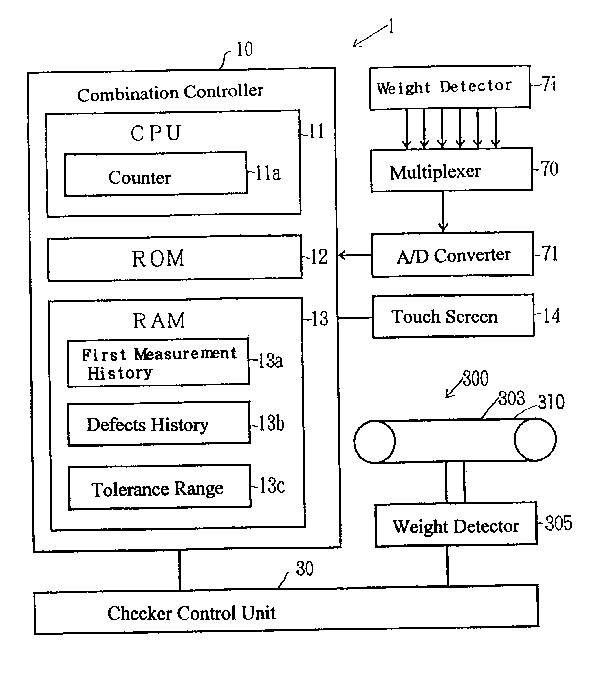
As shown in FIG. 9, the combination controller 10 for the combination weighing system and the checker control unit 30 for the weight checking system, respectively, are connected with machine component parts such as an actuator and a motor through an interface not shown. The combination controller 10 and the checker control unit 30 are connected with each other through an interface not shown.

The checker control unit 30 includes a microcomputer 35, a weight detecting circuit 306, a product detecting circuit 307 and a motor control circuit 309. The weight detecting circuit 306 and the motor control circuit 309 are connected with the microcomputer 35 through an interface not shown. The weight detecting circuit 306 is connected with a weight detector 305 for receiving a weight signal from such weight detector 305.

The product detecting circuit 307 is connected with a good detecto...

first embodiment

The remote controller 50 includes a central processing unit (CPU) 51, a read-only memory (ROM) 52 and a random access memory (RAM) 53. The RAM 53 includes a third measurement history storage 53a, a defects history storage 53b, a tolerance range storage 53c and a times storage 53f. The third measurement history storage 53a is fed (inputted) with the contents stored in the first measurement history storage 13a of the combination controller 10 and the post-discharge measured value Ws and stores the combination calculated value Wc and the post-discharge measured value Ws for the same contents in a fashion associated with each other. In other words, the third measurement history storage 53a stores contents corresponding to the contents stored in the first measurement history storage 13a (FIG. 4A) of the combination controller 10 (FIG. 3) used in the present invention.

The tolerance range storage 53c shown in FIG. 13 stores therein, for example, a predetermined tolerance difference (tolera...

third embodiment

The combination controller 10 shown in FIG. 25A includes the CPU 11, the ROM 12 and the RAM 13. The RAM 13 includes the first measurement history storage 13a in which the contents shown in FIG. 14A is stored as is the case with that in the present invention.

As shown in FIG. 25B, the checker control unit 30 includes a microcomputer 35, a weight detecting circuit 306 and a product detecting circuit 307.

When a product detector 308 detects the product M1, the product detecting circuit 307 shown in FIG. 25B provides the weight detecting circuit 306 with a product detection signal b at a timing matching with the timing of detection of the product M1. Based on the product detection signal b, the weight detecting circuit 306 provides the microcomputer 35 at a predetermined timing with a weight signal c which corresponds to the measured signal from which a vibration component has been eliminated. Based on the weight signal c, the microcomputer calculates the weight of the contents M of the p...


PUM


Abstract

There is provided an abnormal device determining means (CPU 51) which reads a tendency of displacement between the combination calculated weight Wc of the contents M and the post-discharge Ws measured value of the same contents M measured after such contents M have been bagged and which, based on the tendency of displacement so read, determines which one of the combination calculated value Wc and the post-discharge measured value Ws is abnormal, and a display device (54) for displaying a result of the determination. Thus, since based on the displacement tendency of the combination calculated value Wc and the post-discharge measured value Ws, which one of the combination calculated value Wc and the post-discharge measured value Ws is abnormal is determined, it can readily and easily grasped which one of the combination weighing apparatus (1) and the weight checker (300) suffers from a trouble.

Description

1. Field of the InventionThe present invention relates to a combination weighing system, a weight checking system, a weighing system utilizing the both and a weighing, packaging and inspecting system utilizing the weighing system.2. Description of the Prior ArtSuch a combination weighing apparatus as shown in FIG. 2 has hitherto been well known in the art. Referring to FIG. 2, articles M falling by gravity onto a central portion of a dispensing feeder 2 are supplied into a plurality of weighing hoppers 6i through a corresponding number of supply troughs 3i by way of associated pool hoppers 4i. The weighing hoppers 6i are each provided with a weight detector 7i for detecting the weight of the articles M supplied into the corresponding weighing hopper 6i. When a combination of weights of the articles M detected respectively by the weight detectors 7i attains a target weight or an approximate target weight close to the target weight, the articles M contained in some of the weighing hop...

Claims


Application Information

Patent Timeline
Patent Type & Authority Patents(United States)
IPC IPC(8): G01G19/387G01G19/393
CPCG01G15/00G01G23/14G01G19/393
Inventor KONO, KATSUAKINAKAGAWA, YUKIOYAMAGUCHI, YASUSHI
Owner ISHIDA CO LTD
Why Eureka
Try Eureka