Sealing ring

Inactive Publication Date: 2002-04-30
MASCHINENFABRIK SULZE BURCKHARDT AG
View PDF14 Cites 18 Cited by
  • Summary
  • Abstract
  • Description
  • Claims
  • Application Information

AI Technical Summary

Benefits of technology

An advantage of the sealing ring in accordance with the invention is to be seen in the fact that adjacent ring segments respectively have a mutually overlapping joint, so that no straight through-slot is present between the ring segments in a direction extending vertically to the sealing ring, or as the case may be, in a direction axial to the body to be sealed. A sealing ring of this kind has an excellent seal. In a further advantageous embodiment of the sealing ring in accordance with the invention, a cover ring is arranged extending circumferentially externally about the ring segments, which covers over the joints extending between the ring segments in a radial direction from the outside and by this means seals them. The cover ring also serves to mutually stabilize the ring segments. A spring extending in the circumferential direction is advantageously arranged lying on the cover ring at the outside, as for example, a hose spring, or toroidal spring, in order to exert a force acting radially inwardly on the ring segments. The cover ring can, moreover, have a connecting element cooperating with one of the ring segments, in order to prevent a rotation of the cover ring relative to the individual ring segments.
With regard to a rod which is to be sealed, a sealing ring can be developed in such a manner that the individual ring segments have a mutual clearance extending in the circumferential direction of the sealing ring. The sealing ring undergoes progressive wear during the operation on the surface facing the rod. The sealing ring in accordance with the invention has the advantage that, due to the clearance between the individual ring segments and also the hose spring surrounding the sealing ring, the ring segments are constantly subjected to a force acting in a radial direction towards the rod, so that during the progressive wear, the clearance between the ring segments is constantly reduced, wherein the ring segments contact the rod and maintain their sealing function. Moreover, the sealing function of the sealing ring is maintained in the axial direction by means of the overlapping joints.
A sealing ring comprising at least two ring segments as well as a cover ring extending circumferentially at the outside has the advantage that, due to the combination of overlapping joint and circumferentially extending cover ring at the outside, a very good sealing action in the axial direction results, and also that only a single sealing ring is required for sealing in the axial direction, so that the sealing ring has a low constructional height in the axial direction. A further advantage of the sealing ring in accordance with the invention is to be seen in that a relatively stiff material can also be used as material for the ring segments, so that a high temperature polymer, such as, for example, modified PEEK can also be used as a material for the ring segments.
A further advantage of the sealing ring is to be seen in the fact that due to its type of construction an installation of the ring with an already installed piston rod is possible and not problematic.

Problems solved by technology

This known sealing ring has the disadvantage that to seal the through-slot in the axial direction, two sealing rings are respectively to be arranged in pairs adjacent one another.
A further disadvantage is to be seen in that a pair of sealing rings arranged adjacent one another has a relatively large extent in the axial direction, which brings about an increased frictional heat.
This frictional heat is moreover difficult to dissipate because the sealing ring is usually manufactured from plastic and has a low thermal conductivity, which prevents the transport of heat from the body to be sealed to an external cooling device.
The sealing ring undergoes progressive wear during the operation on the surface facing the rod.

Method used


Image

  • Sealing ring
  • Sealing ring
  • Sealing ring

Examples


Embodiment Construction

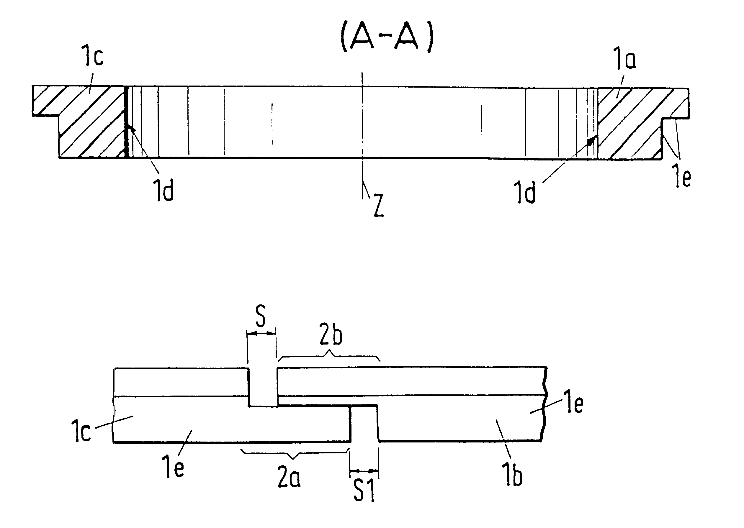
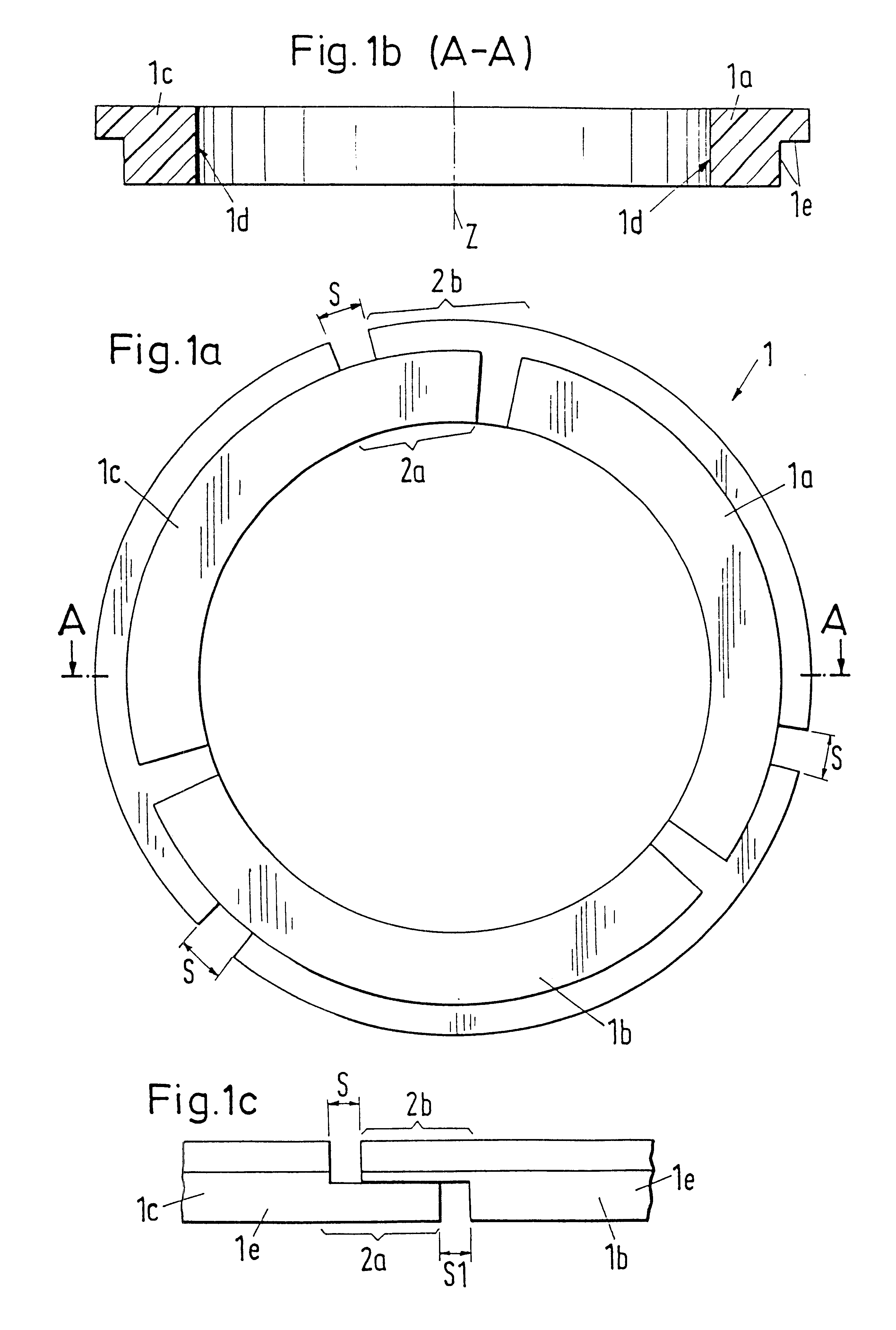
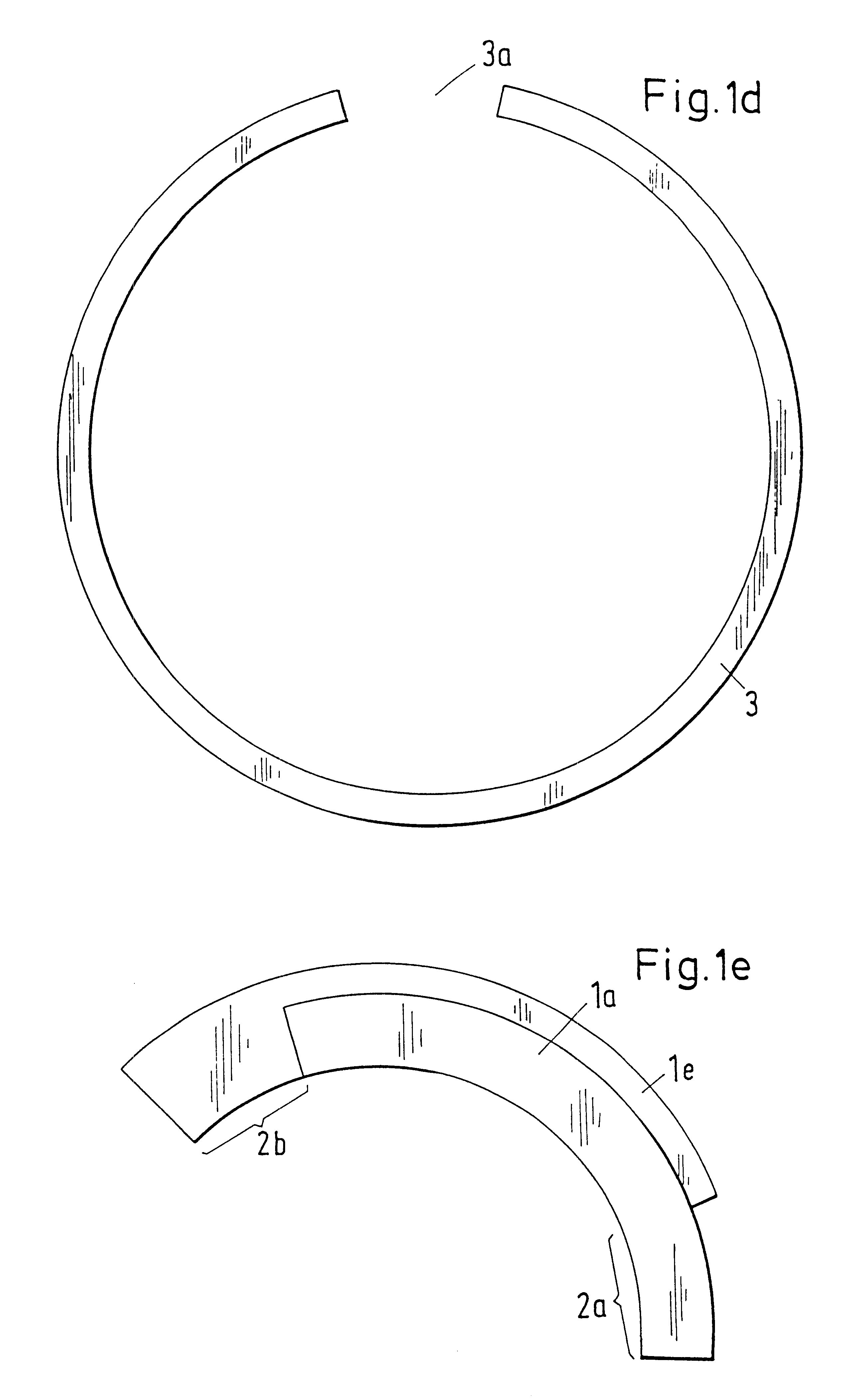
FIG. 1a shows a sealing ring 1 designed as a multiple part ring with three ring segments 1a, 1b, 1c. The individual ring segments 1a, 1b, 1c have mutual joints, with a mutual clearance S, extending in the circumferential direction of the sealing ring 1. The segments 1a, 1b, 1c have portions 2a, 2b extending in the circumferential direction, which form an overlapping joint. FIG. 1b shows a section through FIG. 1a along the line A--A. The ring segments 1a, 1c have a sliding surface 1d oriented towards the center Z of the sealing ring, which lies on the surface to be sealed with circular cross-section, for example of a piston rod or is spaced from it by a small distance. In the present embodiment, the ring segments 1a, 1c are developed in an L-shape in the illustrated cross-section and have a rectangular recess 1e. This recess 1e serves to receive a cover ring 3 illustrated in FIG. 1d, which is designed in such a way from the point of view of its dimensions that it has a cross-section ...


PUM


Abstract

The invention relates to a sealing ring for sealing a piston rod of a piston compressor. The sealing ring comprises three segments, wherein the segments have portions extending in the circumferential direction of the sealing ring, which form an overlapping joint. The overlapping joint brings about an excellent sealing effect in the axial direction.

Description

1. Field of the InventionThe invention relates to a sealing ring that comprises at least two segments running in a circumferential direction forming an overlapping joint.2. Description of the Prior ArtA multiple-part sealing ring made up of three ring segments is known from the patent CH 439 897. The gaps of the ring segments form a through slot extending in the axial direction. Such sealing rings are usually arranged in pairs in series one behind the other and form a so-called packing, in order to seal the sliding surface of a body which is to be sealed, for example, a piston rod of a piston compressor. This known sealing ring has the disadvantage that to seal the through-slot in the axial direction, two sealing rings are respectively to be arranged in pairs adjacent one another. A further disadvantage is to be seen in that a pair of sealing rings arranged adjacent one another has a relatively large extent in the axial direction, which brings about an increased frictional heat. Thi...

Claims


Application Information

Patent Timeline
IPC IPC(8): F16J9/00F16J15/16F16J9/16F16J15/26
CPCF16J15/26F16J9/16
Inventor FEISTEL, NORBERT
Owner MASCHINENFABRIK SULZE BURCKHARDT AG
Why Eureka
Try Eureka