Mobile concrete saw

a concrete saw and mobile technology, applied in the direction of manufacturing tools, roads, roads, etc., can solve the problems of insufficient mobility of single bladed saws for cutting wide grooves, inability to form the required groove along the side edges of slabs, and inability to cut kerfs. the effect of convenient transportation

Inactive Publication Date: 2002-05-21
COLLINS LOUIS M +1
View PDF19 Cites 29 Cited by
  • Summary
  • Abstract
  • Description
  • Claims
  • Application Information

AI Technical Summary

Benefits of technology

In accordance with one aspect of the present invention there is provided a cured-concrete-cutting saw which is sufficiently mobile as facilitates its transport to a work site located within a building, for example, and which is useful in cutting block-out grooves for expansion joints between adjacent sides of adjacent concrete slabs and / or troughs in the surface of such slabs. The saw includes a housing, a blade assembly comprising a plurality of circular blades disposed in spaced apart parallel relation to one another on the outboard end of a shaft that is mounted on the bottom of the housing. A motor provides power for rotation of the shaft and its blade assembly and, optionally, power for propelling the saw over the top surface of a concrete slab. A mechanism is provided at a position adjacent the aft end of the saw for operator adjustment of the depth of cut of the blades of the blade assembly. Through the means of selecting different diameter blades for the make-up of a blade assembly, the saw may be employed to cut block-outs or troughs of different cross-sectional geometries, in the top surface of a concrete slab.

Problems solved by technology

When employing either rigid forms or a "moving" form in the pouring of a concrete slab, it is impractical, or even impossible to form the required groove along the side edges of a slab for receipt of the wings of the expansion joint.
The blades of these saws are limited to cutting a kerf which is relatively small in width, usually between about 1 / 8 and about 3 / 8 inch in width, due to the cost of manufacture of wider blades.
Use of a single bladed saw for cutting wide grooves is inordinately time-consuming in that multiple passes of the saw blade along the length of the groove must be employed to achieve the desired width of the groove.
Known multi-bladed concrete saws are limited to hand-held devices which are restricted in their maximum depth of cut, speed of cutting, and overall efficiency.
However, due to their relative fragile construction, which is required to permit them to be hand-held, these devices are not suitable for cutting grooves of extended length such as in concrete slabs or the like.
All known self-propelled concrete saws, aside from the massive highway surface groove-cutting machines which are unsuitable in size and mobility for use in cutting block-outs or troughs in concrete slabs, employ only a single blade.

Method used


Image

  • Mobile concrete saw
  • Mobile concrete saw
  • Mobile concrete saw

Examples


Embodiment Construction

As used herein, a "mobile" saw refers to a saw which is of a size and design which causes the saw to be readily transported between work sets, manipulated, normally by an operator walking behind the saw, between work locations at a work site including passage through door openings of less then about 40 inches in opening width, and in the course of cutting kerfs in the top surface of a cured concrete slab.

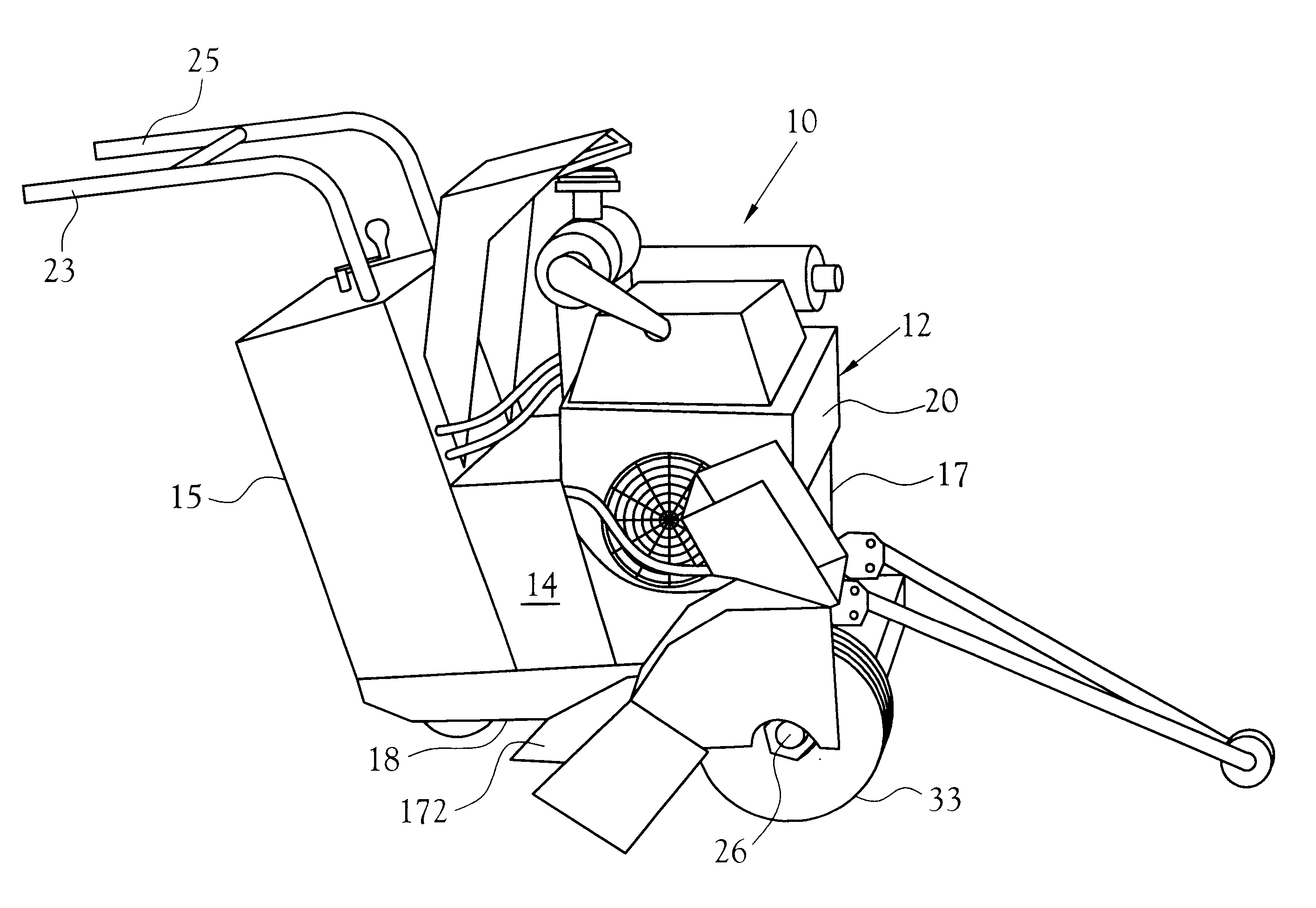
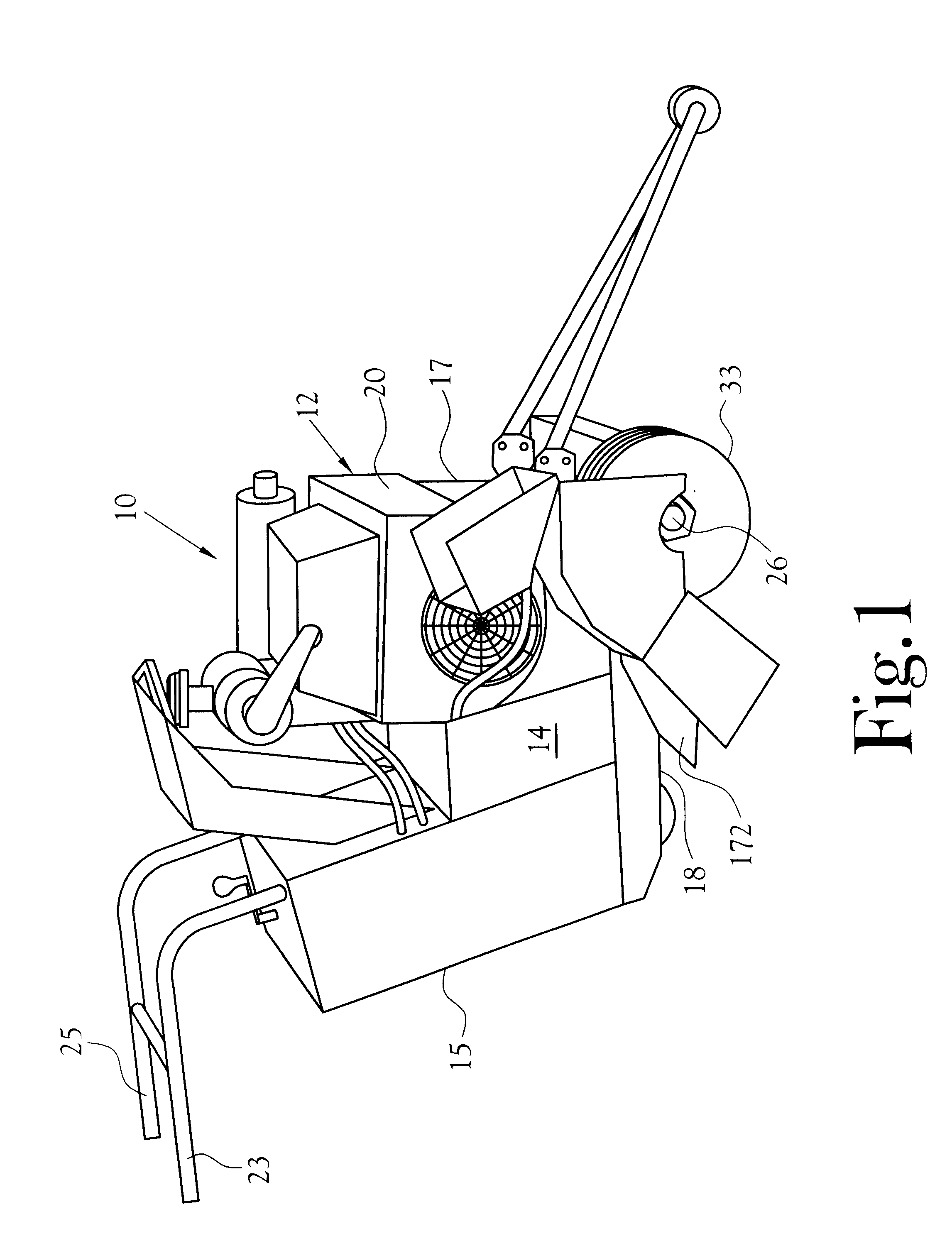
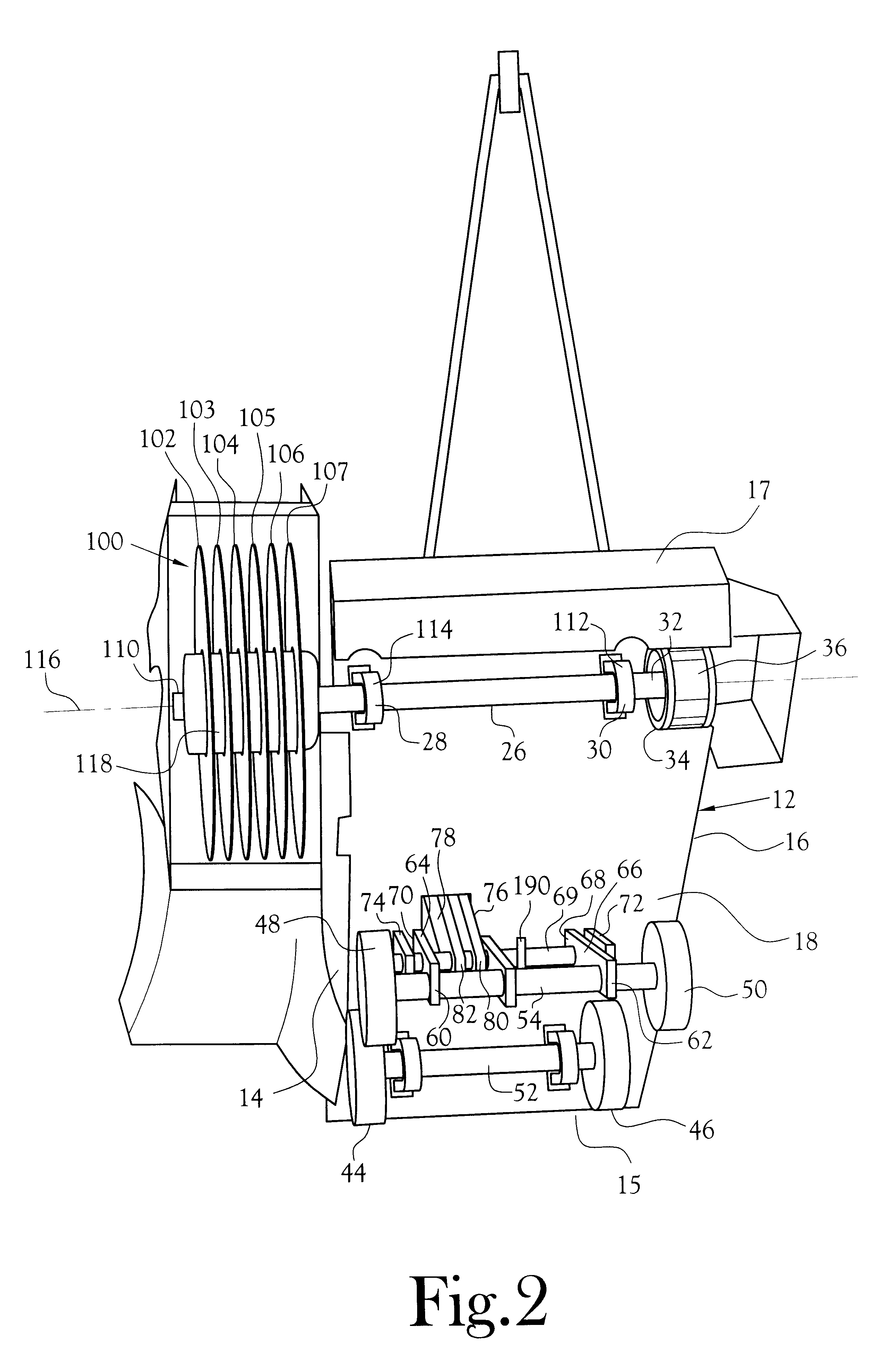
Referring to the several Figures, and initially FIGS. 1 and 2, one embodiment of a mobile saw 10 including various of the features of the present invention includes a multi-compartmental housing indicated generally at 12 having opposite sides 14,16 aft and front ends 15,17, respectively and a bottom 18. A portable engine 20, such as a gas-powered small implement engine of about five horsepower, is mounted to the housing and includes an output shaft, having a pulley mounted thereon. A driven shaft 26 is journalled 28,30 on the bottom of the housing adjacent the forward end 17 of the ...


PUM

PropertyMeasurementUnit
thicknessaaaaaaaaaa
widthaaaaaaaaaa
lengthaaaaaaaaaa

Abstract

A cured-concrete-cutting saw which is sufficiently mobile as facilitates its transport to a work site located within a building, and between work sites within a building, for example, and which is useful in cutting block-out grooves for expansion joints between adjacent sides of adjacent concrete slabs and/or troughs in the surface of such slabs. The saw includes a housing, a blade assembly comprising a plurality of circular blades disposed in spaced apart parallel relationship to one another on the outboard end of a driven shaft that is mounted on the bottom of the housing. A motor provides power for rotation of the shaft and its blade assembly. Optionally, the motor provides power for propelling the saw over the top surface of a concrete slab. A mechanism is provided for operator adjustment of the depth of cut of the blades of the blade assembly from a position adjacent the aft end of the saw. Through the means of selecting different diameter blades for the blade assembly, the saw may be employed to cut a variety of block-outs or troughs of different cross-sectional geometries, in the top surface of a concrete slab. A method is disclosed for the formation of an elongated block-out or trough in the top surface of a cured concrete slab for the preparation of adjacent side margins of adjacent sides of adjacent concrete slabs and for the installation of an expansion strip in the space between these adjacent sides.

Description

This invention relates to saws for cutting grooves or the like in the surface of concrete slabs, particularly cured concrete slabs, such as in the top surface of the concrete floor of a building or the like.BACKGROUND OF INVENTIONConcrete floors, commercial-sized vehicle garage floor surfaces, for example, and the like are commonly poured in slabs, a slab being a substantially planar expanse of concrete of a given thickness, commonly less than eight inches, whose side dimensions are commonly defined through the use of rigid forms that are removed after the concrete has cured sufficiently. In certain concrete slab pouring operations, the concrete is sufficiently self-supporting as poured so that a "moving" form may be employed, thereby speeding up the overall process.Expansion joints are commonly deployed between adjacent sides of adjacent slabs to accommodate expansion of the concrete in response to climatic conditions and other external influences. These expansion joints are not to...

Claims


Application Information

Patent Timeline
Patent Type & Authority Patents(United States)
IPC IPC(8): B23D45/10B28D1/30B28D1/04B23D45/00B28D1/02B28D1/00E01C23/088E01C23/00
CPCB23D45/10E01C23/088B28D1/30B28D1/045E01C23/0933E01C23/0986
Inventor COLLINS, LOUIS M.JENKINS, RICK
Owner COLLINS LOUIS M
Why Eureka
Try Eureka