
Marking press device for producing raised symbols with or without coloring

a marking press and raised symbol technology, applied in the field of marking press devices, can solve the problems of difficult replacement of spools, difficulty in issuing cards, and inability to perform only pressing without coloring, and achieve the effect of convenient and simplified changing

Inactive Publication Date: 2002-06-04
SANKYO SELKI MFG CO LTD
View PDF7 Cites 12 Cited by
  • Summary
  • Abstract
  • Description
  • Claims
  • Application Information

AI Technical Summary

Benefits of technology

It therefore is an object of the present invention to provide a marking press device that provides for convenient and simplified changing of ribbon supplying spool and ribbon winding spool.
Finally, in accordance with the present invention, raised-dot cells used for embossing frequently used Braille dot patterns and a recessed-dot cell having six recesses are made in a plurality of pairs and retained in the device in addition to the six primary pairs. Therefore, a one-time operation can save multiple-time operations which a raised-dot cell having only a single raised dot needs to perform to produce a complete Braille dot pattern for a character.

Problems solved by technology

Thus, it has been difficult to replace the spools.
In this case, the ribbon may be set in a wrong route or inside out, causing problems in issuing cards.
Therefore, it is impossible to perform only pressing without coloring, or even if possible, it mostly requires considerably troublesome work of, for example, detaching (dismounting) the inked ribbon.
For this reason, it has been difficult to employ such a marking press device configured as above for general uses.
As a consequence, the weight of the marking press device itself has been very heavy.
In such a large device, the number of necessary types is considerably large.

Method used


Image

  • Marking press device for producing raised symbols with or without coloring
  • Marking press device for producing raised symbols with or without coloring
  • Marking press device for producing raised symbols with or without coloring

Examples


Embodiment Construction

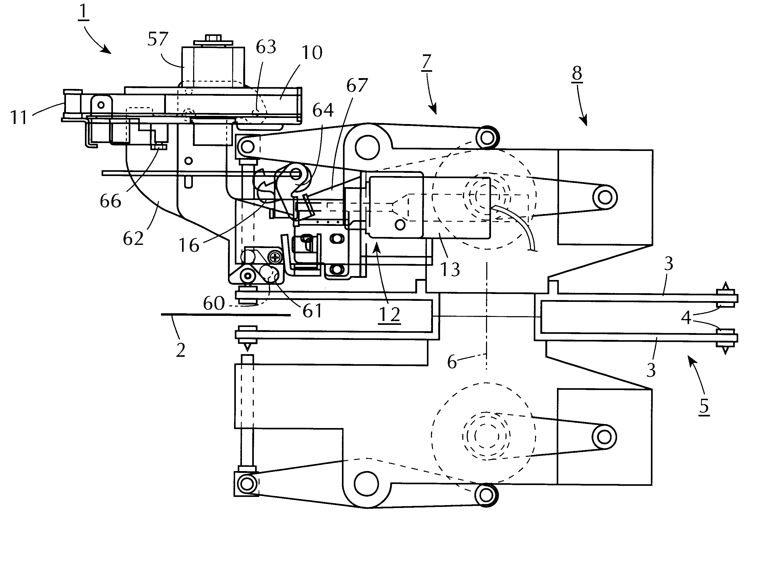
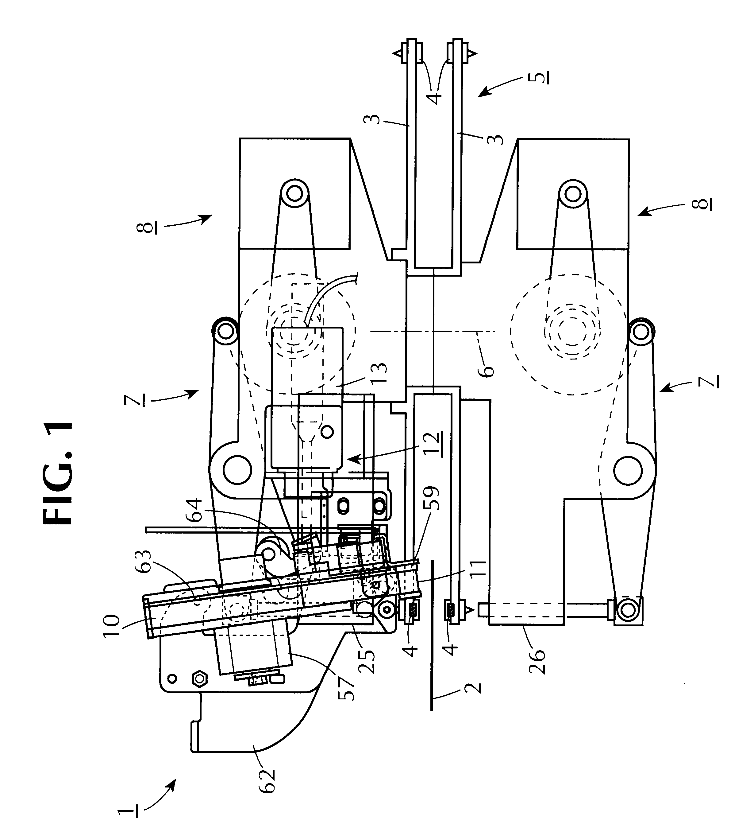
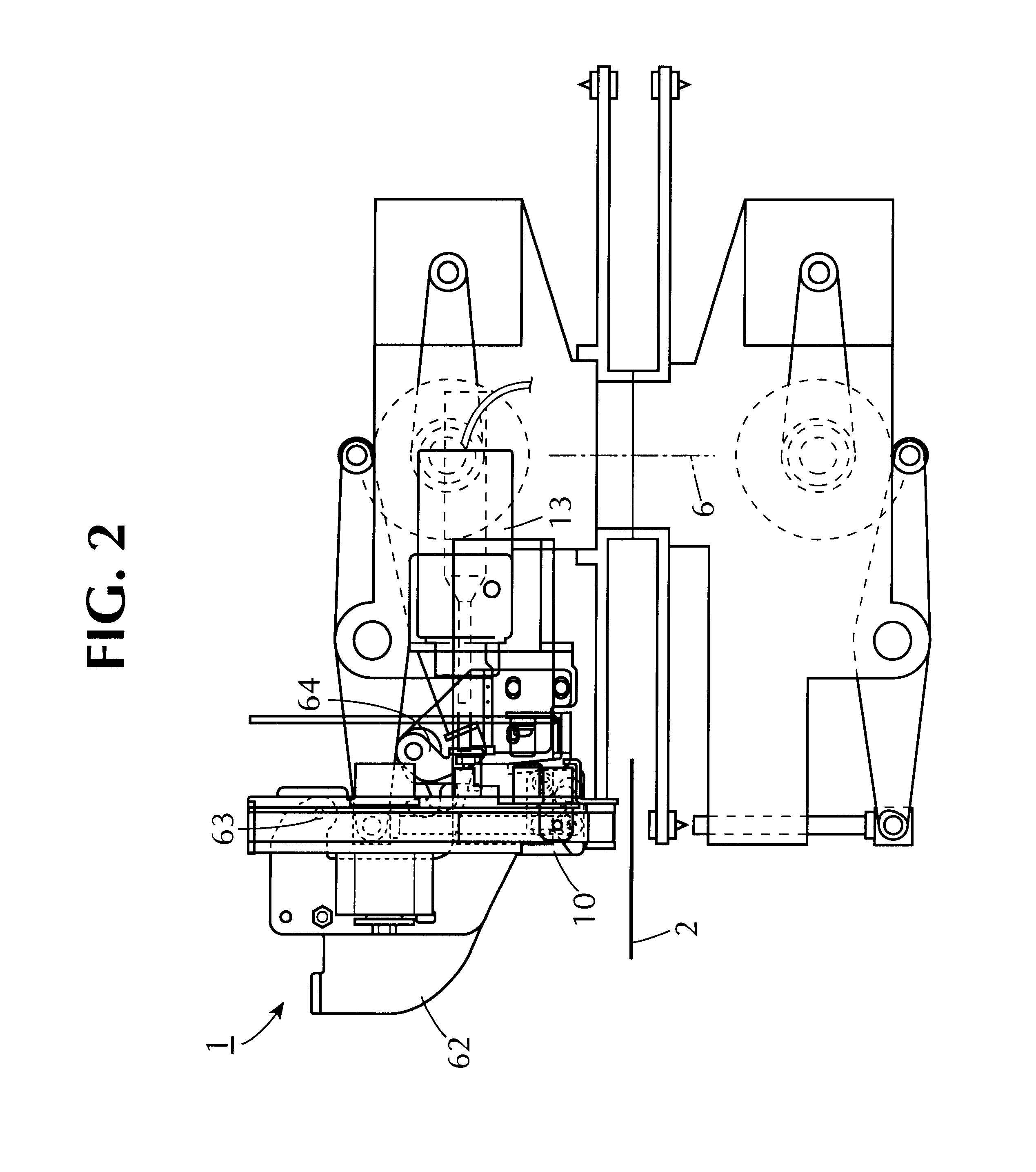
FIGS. 1-9 show an embodiment of a marking press device of the present invention. A marking press device 1 presses characters and the like onto a workpiece 2 such as a credit card (simply, "card" herein). As shown in FIG. 1, the marking press device comprises a pair of type arms 3, 3 that face each other to interpose a workpiece 2 therebetween, a type 4 that is fixed on each type arm 3 and makes a mark thereof, a circular type assembling member 5 to which a plurality of type arms 3 are attached radially, a pressing means 7 that supports the type assembling member 5 rotatable around a rotary shaft 6 and presses a selected type 4 from the type assembling member 5 onto the workpiece 2, and a driving means 8 that rotates the type assembling member 5. Note that the characters and the like here indicate hiragana, katakana, Chinese characters, alphabets, symbols, or drawings.

The marking press device 1 also comprises a ribbon guiding mechanism 9, a ribbon frame 10 to which the ribbon guiding...


PUM


Abstract

A marking press device having a pair of type arms that face each other to interpose a workpiece to be marked therebetween, a type fixed on each of said type arms for making a mark thereof, a circular type assembling member around which a plurality of said type arms are attached radially, a device for rotatably supporting said type assembling member around a rotary shaft and for pressing a selected type from said type assembling member onto said workpiece, a driver for rotating said type assembling member, a ribbon guiding mechanism that guides an inked ribbon for coloring marked characters, a ribbon supplying spool for supplying said inked ribbon, a ribbon winding spool for winding said inked ribbon, a ribbon frame to which said ribbon guiding mechanism, said ribbon supplying spool and said ribbon winding spool are mounted, and ribbon frame turning device for rotatably supporting said ribbon frame and turning said ribbon frame to a horizontal position above said type arms when said inked ribbon is replaced.

Description

The present invention relates to a marking press device.Marking and pressing of characters, symbols, numbers or figures includes a technique of so-called indenting and another technique of so-called embossing. Indenting produces indented marks that correspond to raised types by placing and pressing a workpiece between a pressing member having a raised type at a front end and a flat pressing member positioned opposite the pressing member. Embossing produces embossed marks that correspond to raised types by placing and pressing a workpiece between a pressing member having a raised type at a front end thereof and an oppositely placed recessed marking member.A general embossing involves a topping, i.e., a coloring of the front surface of the characters. Also, a general indenting involves a coloring of grooved bottoms of the indented characters with ink.An inked ribbon may be used for coloring such indented characters. In such a marking press device, a workpiece and a inked ribbon are to...

Claims


Application Information

Patent Timeline
Patent Type & Authority Patents(United States)
IPC IPC(8): B41J35/28B44B5/00
CPCB41J35/28B44B5/0076B44B5/0071
Inventor KOZAKAI, MASAHIROYOKOZAWA, MITSUO
Owner SANKYO SELKI MFG CO LTD
Learn More