Magnetoresistive effect multi-layered structure and thin-film magnetic head with the magnetoresistive effect multi-layered structure

a multi-layered structure and magnetoresistive effect technology, applied in the field of thin-film magnetic head with the magnetoresistive effect multi-layered structure, can solve the problems that no one has approached to control the magnetic characteristics of the pinned ferromagnetic layer itself, and proper anisotropy control cannot be expected

Inactive Publication Date: 2002-06-04
TDK CORPARATION
View PDF10 Cites 11 Cited by
  • Summary
  • Abstract
  • Description
  • Claims
  • Application Information

AI Technical Summary

Problems solved by technology

This degradation is caused by the high temperature stress during operation of the HDD unit and by the magnetic field by a hard magnet layer used for giving a bias magnetic field to the free layer.
However, no one has approached to control the magnetic characteristics of the pinned ferromagnetic layer itself to stabilize the pinned direction.
Actually, if the layer of NiFe is formed with a thickness less than 0.5 nm, the layer may be shaped in islands and thus proper anisotropy control cannot be expected.

Method used


Image

  • Magnetoresistive effect multi-layered structure and thin-film magnetic head with the magnetoresistive effect multi-layered structure
  • Magnetoresistive effect multi-layered structure and thin-film magnetic head with the magnetoresistive effect multi-layered structure
  • Magnetoresistive effect multi-layered structure and thin-film magnetic head with the magnetoresistive effect multi-layered structure

Examples


second example

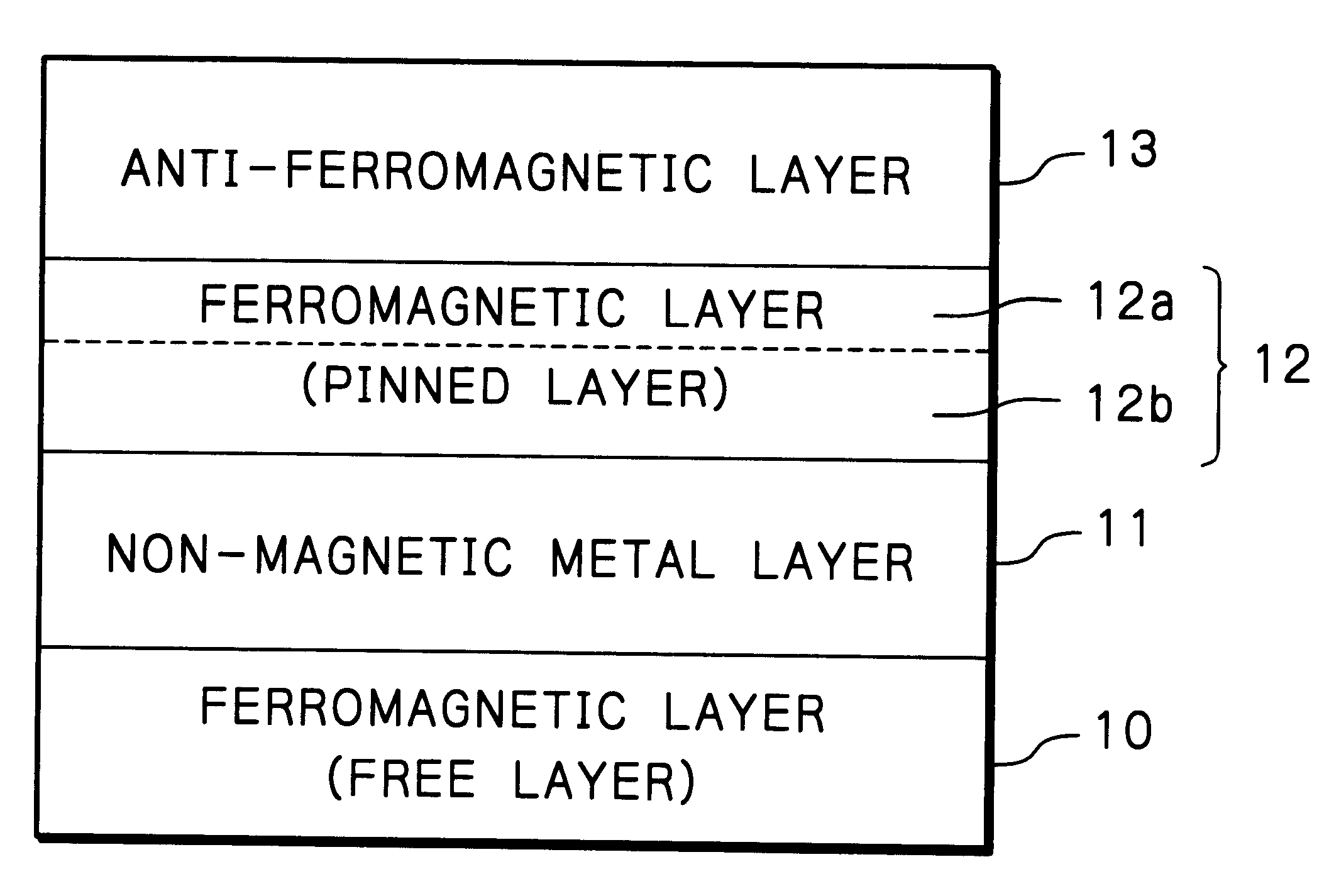
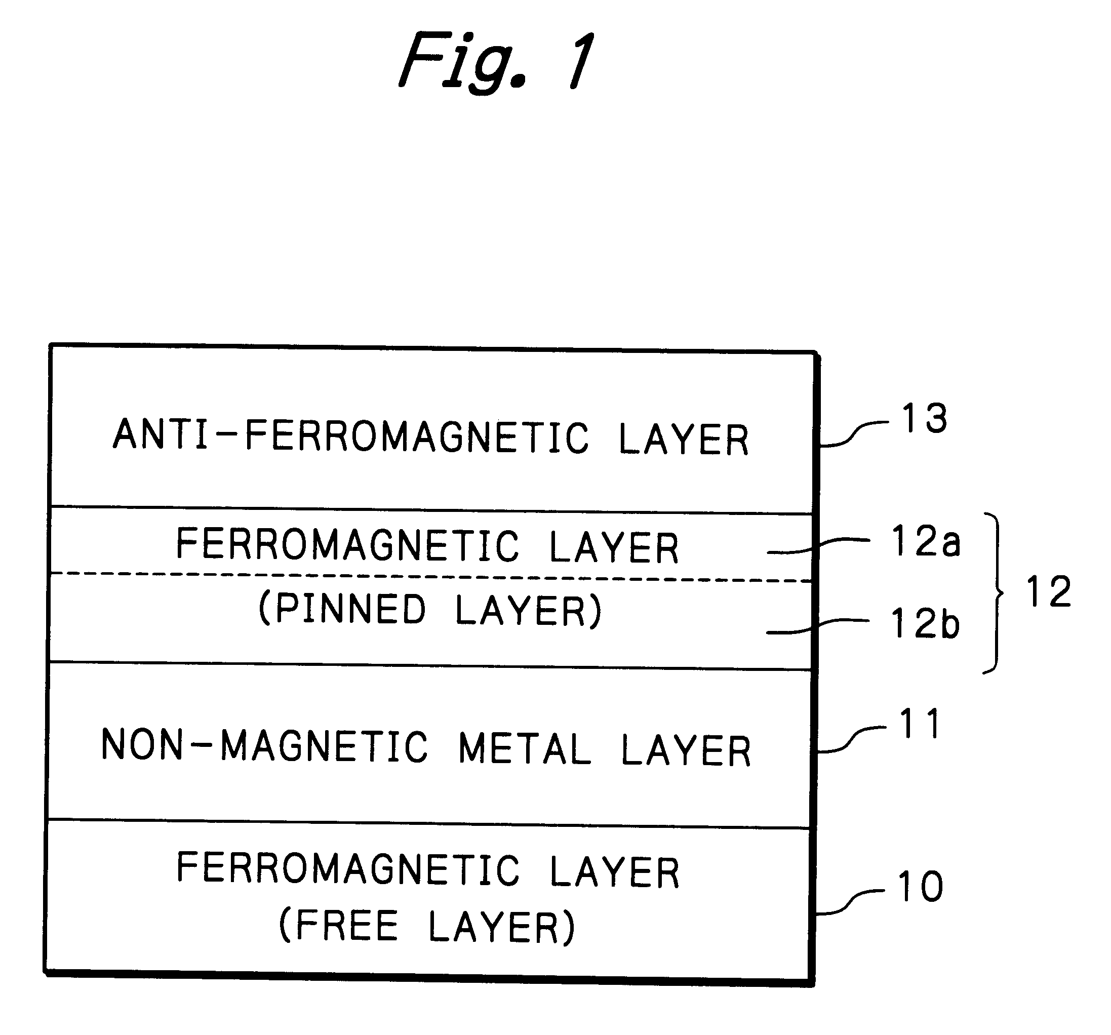
A second example of the multi-layered spin valve effect structure as illustrated in FIG. 1 was actually fabricated by depositing multi-layers under application of magnetic field without heating the substrate. Concretely, the multi-layered structure was formed by sequentially depositing, on the substrate of AlTiC, an under layer of Ta with the thickness of 5.0 nm, a ferromagnetic material layer (free layer) 10 composed of a NiFe layer with the thickness of 9.0 nm and a Co layer with the thickness of 1.0 nm, a non-magnetic metallic material layer 11 of Cu with the thickness of 3.0 nm, a ferromagnetic material layer (pinned layer) 12 having a two layered structure composed of a ferromagnetic material layer 12b of Co.sub.90 Fe.sub.10 (Co is 90 at % and Fe is 10 at %) with the thickness of 1.0 or 2.0 nm and a ferromagnetic material layer 12a of Ni.sub.80 Fe.sub.20 (Ni is 80 at % and Fe is 20 at %) with the thickness of 0-4.0 nm, which has a smaller magnetic anisotropy than that of Co, an...

third example

A third example of the multi-layered spin valve effect structure as illustrated in FIG. 1 was actually fabricated by depositing multi-layers under application of magnetic field without heating the substrate. Concretely, the multi-layered structure was formed by sequentially depositing, on the substrate of AlTiC, an under layer of Ta with the thickness of 5.0 nm, a ferromagnetic material layer (free layer) 10 composed of a NiFe layer with the thickness of 9.0 nm and a Co layer with the thickness of 1.0 nm, a non-magnetic metallic material layer 11 of Cu with the thickness of 3.0 nm, a ferromagnetic material layer (pinned layer) 12 having a two layered structure composed of a ferromagnetic material layer 12b of Co with the thickness of 1.0 or 2.0 nm and a ferromagnetic material layer 12a of Ni.sub.80 Fe.sub.20 (Ni is 80 at % and Fe is 20 at %) with the thickness of 0-4.0 nm, which has a smaller magnetic anisotropy than that of Co, and an anti-ferromagnetic material layer 13 of RuRhMn ...

fourth example

A fourth example of the multi-layered spin valve effect structure as illustrated in FIG. 1 was actually fabricated by depositing multi-layers under application of magnetic field without heating the substrate. Concretely, the multi-layered structure was formed by sequentially depositing, on the substrate of AlTiC, an under layer of Ta with the thickness of 5.0 nm, a ferromagnetic material layer (free layer) 10 composed of a NiFe layer with the thickness of 9.0 nm and a Co layer with the thickness of 1.0 nm, a non-magnetic metallic material layer 11 of Cu with the thickness of 3.0 nm, a ferromagnetic material layer (pinned layer) 12 having a two layered structure composed of a ferromagnetic material layer 12b of Co with the thickness of 1.0 or 2.0 nm and a ferromagnetic material layer 12a of Ni.sub.80 Fe.sub.20 (Ni is 80 at % and Fe is 20 at %) with the thickness of 0-4.0 nm, which has a smaller magnetic anisotropy than that of Co, and an anti-ferromagnetic material layer 13 of FeMn w...


PUM

PropertyMeasurementUnit
thicknessaaaaaaaaaa
thicknessaaaaaaaaaa
thicknessaaaaaaaaaa

Abstract

A MR multi-layered structure or a thin-film magnetic head with the MR multi-layered structure includes a non-magnetic electrically conductive material layer, first and second ferromagnetic material layer separated by the non-magnetic electrically conductive material layer, and an anti-ferromagnetic material layer formed adjacent to and in physical contact with one surface of the second ferromagnetic material layer, the one surface being in opposite side of the non-magnetic electrically conductive material layer. The second ferromagnetic material layer includes a first layer of a ferromagnetic material containing Co, and a second layer of a ferromagnetic material with a smaller magnetic anisotropy than that of Co.

Description

The present invention relates to a magnetoresistive effect (MR) multi-layered structure especially using giant magnetoresistive effect (GMR) such as spin valve effect, and a thin-film magnetic head with the MR multi-layered structure used for a HDD (Hard Disk Drive) unit.DESCRIPTION OF THE RELATED ARTRecently, thin-film magnetic heads with MR sensors based on spin valve effect of GMR characteristics are proposed (U.S. Pat. Nos. 5,206,590 and 5,422,571) in order to satisfy the requirement for ever increasing data storage densities in today's magnetic storage systems like HDD units. The spin valve effect thin-film structure includes first and second thin-film layers of a ferromagnetic material separated by a thin-film layer of non-magnetic metallic material, and an adjacent layer of anti-ferromagnetic material is formed in physical contact with the second ferromagnetic layer to provide exchange bias magnetic field by exchange coupling at the interface of the layers. The magnetization ...

Claims


Application Information

Patent Timeline
Patent Type & Authority Patents(United States)
IPC IPC(8): G11B5/66G11B5/39
CPCG11B5/66Y10T428/1121
Inventor SHIMAZAWA, KOJISASAKI, TETSUROOHTA, MANABU
Owner TDK CORPARATION
Why Eureka
Try Eureka