
Method and system for re-routing interconnects within an integrated circuit design having blockages and bays

a technology of interconnections and integrated circuits, applied in the field of data processing, can solve the problems that buffers cannot be placed on top of pre-existing circuit macros known as blockages, and no buffer insertion algorithm that follows the conventional steiner tree routing topology will be able to find a solution

Inactive Publication Date: 2002-06-04
IBM CORP
View PDF2 Cites 134 Cited by
  • Summary
  • Abstract
  • Description
  • Claims
  • Application Information

AI Technical Summary

Problems solved by technology

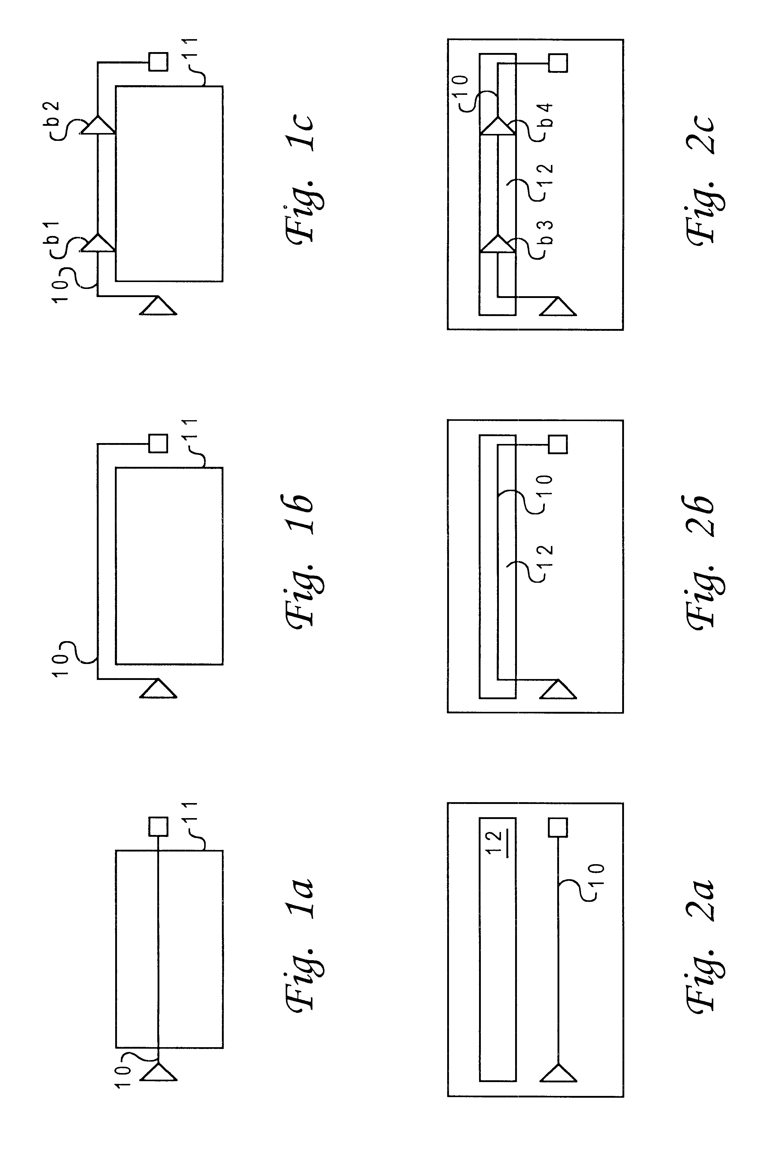
When inserting buffers into a previously routed interconnect network (especially a hierarchical one), a buffer typically cannot be placed on top of a pre-existing circuit macro known as a blockage.
Thus, if the interconnect network was routed mostly over one or more blockages, then no buffer insertion algorithm that follows the conventional Steiner tree routing topology will be able to find a solution.

Method used


Image

  • Method and system for re-routing interconnects within an integrated circuit design having blockages and bays
  • Method and system for re-routing interconnects within an integrated circuit design having blockages and bays
  • Method and system for re-routing interconnects within an integrated circuit design having blockages and bays

Examples


Embodiment Construction

A. Problem Formulation

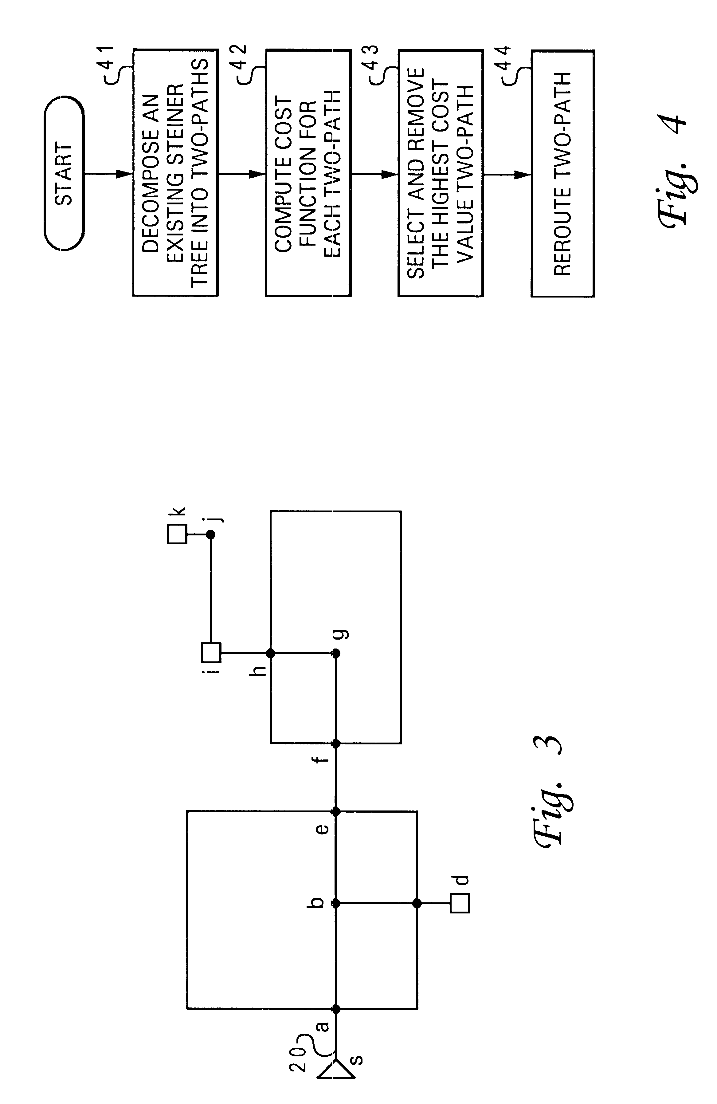
Given a unique source so and a set of sinks SI, a rectilinear Steiner tree T(V,E) is a spanning tree in a rectilinear plane that connects every node in {so} u SI along with additional nodes. Let W be the set of these additional nodes, so that V={so} U SI U W. W may include three types of nodes: (i) internal Steiner nodes of degree three or four, denoted by a set IN, (ii) corner nodes of degree two that designate a path switch from a horizontal to a vertical direction, denoted by a set CO, and (iii) boundary nodes of degree two with one incident edge routed over blockages while the other avoids blockages, denoted by a set BY. For example, as shown in FIG. 3, there is depicted a Steiner tree route 20 having a source so=s and sinks SI={d,i,k}. All the other nodes are in W with b .di-elect cons. IN, g, j .di-elect cons. CO, and a, c, e, f, h .di-elect cons. BY.

A rectangle r has a unique bounding coordinates (x.sub.1 y.sub.1), (x.sub.2, y.sub.2), whereby x.sub.1.lto...


PUM


Abstract

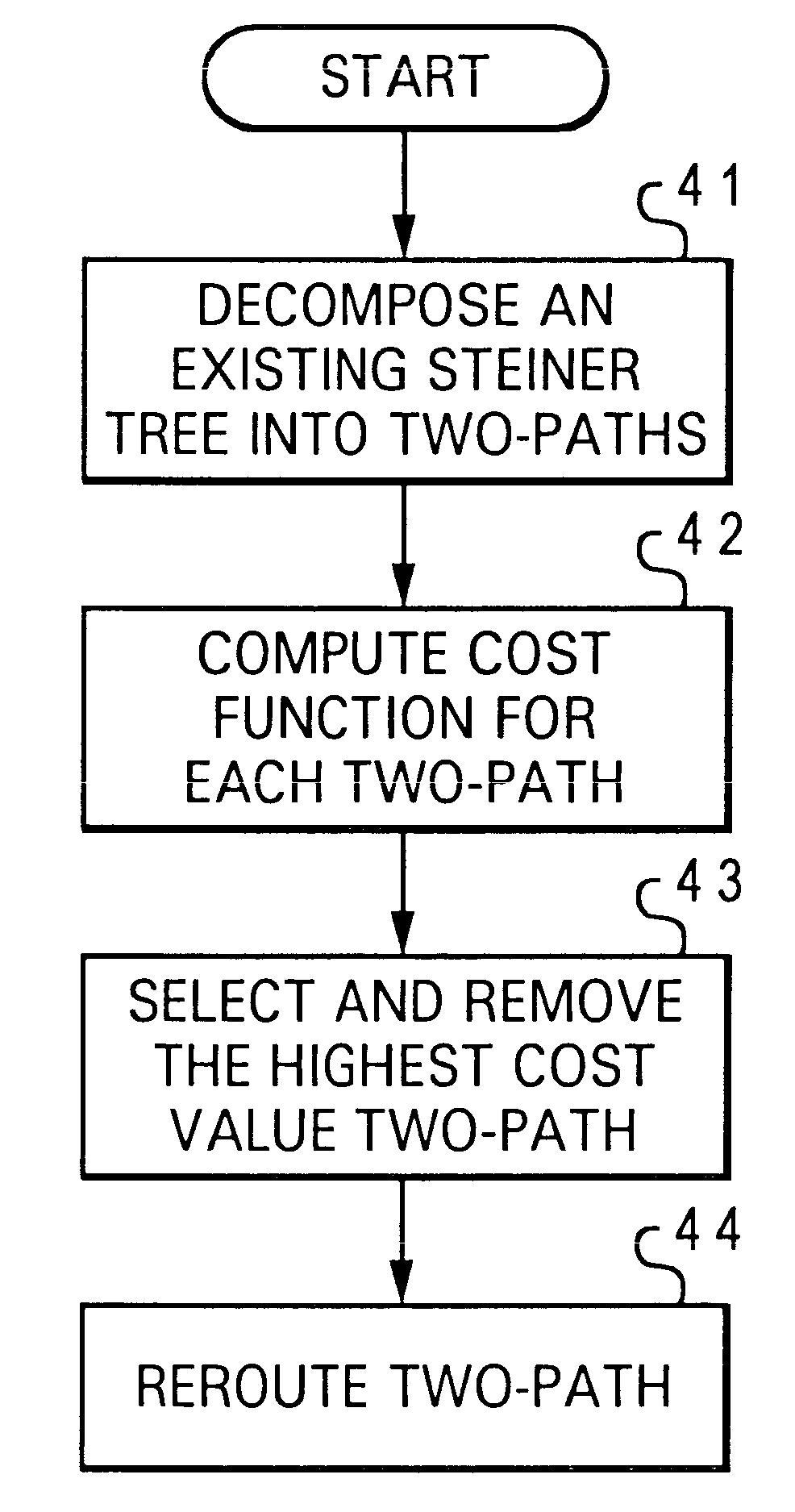
A method and system for re-routing interconnects within an integrated circuit design having blockages and bays is disclosed. A net within the integrated circuit design is initially decomposed into multiple two-paths. The net includes interconnects previously routed by utilizing a Steiner tree routing algorithm. Next, a cost associated with each of the two-paths is calculated. A two-path having a a high cost is subsequently selected and re-routed with a lower cost two-path.

Description

1. Technical FieldThe present invention relates to a method and system for data processing in general, and in particular to a method and system for routing interconnects within an integrated circuit design. Still more particularly, the present invention relates to a method and system for re-routing interconnects within an integrated circuit design having blockages and buffer bays.2. Description of the Prior ArtAs integrated circuits become increasingly smaller, the resistance per unit length of interconnect continues to increase, but the capacitance per unit length of interconnect remains almost constant while logic delay continues to decrease. If this trend continues, interconnect delay will become more dominant than logic delay in the near future.Generally speaking, the characteristic interconnect delay of an interconnect is directly proportional to the square of the length of the interconnect. One approach to reducing interconnect delay is to insert buffers along the interconnect...

Claims


Application Information

Patent Timeline
Patent Type & Authority Patents(United States)
IPC IPC(8): G06F17/50
CPCG06F17/5077G06F30/394
Inventor ALPERT, CHARLES JAYGANDHAM, RAMA GOPALHU, JIANGNEVES, JOSE LUISQUAY, STEPHEN THOMAS
Owner IBM CORP
Learn More