System, method and apparatus for dynamic path protection in networks

a dynamic path and network protection technology, applied in the field of communication, can solve the problems of multiple links failing simultaneously, algorithms failing, and working paths and protection paths subject to wavelength continuity constraints

Inactive Publication Date: 2005-10-27
BOARD OF RGT THE UNIV OF TEXAS SYST
View PDF21 Cites 56 Cited by
  • Summary
  • Abstract
  • Description
  • Claims
  • Application Information

AI Technical Summary

Benefits of technology

[0013] Furthermore, the present invention provides an apparatus for finding two paths between a source node and a destination node in a network having multiple nodes and multiple links that includes a processor and one or more communication interfaces communicably coupled to the processor that are capable of communicating with the network. The processor is capable of finding a first path between the source node and the destination node using a routing algorithm and a model of the network wherein each link has a cost and at least one risk identifier and the cost of the links having one or more risk identifiers that occur more than once in the network model are increased, modifying the network model by removing all links in the first path and all links having one or more risk identifiers in common with any of the risk identifiers of the links in the first path, and finding a second path between the source node and the destination node using the routing algorithm and the modified network model.

Problems solved by technology

In the first problem, a network without wavelength converters is considered; thus both the working path and protection path are subject to the wavelength continuity constraint.
Existing polynomial time algorithms can be applied to find a pair of link-disjoint lightpaths on a single wavelength; however, such algorithms fail if the working and protection lightpaths are on two different wavelengths.
Yet a single risk factor can cause multiple links to fail simultaneously.
The problem becomes finding link-disjoint lightpaths that are also risk disjoint.
The cost of the links having one or more risk identifiers that occur more than once in the network model are increased.

Method used


Image

  • System, method and apparatus for dynamic path protection in networks
  • System, method and apparatus for dynamic path protection in networks
  • System, method and apparatus for dynamic path protection in networks

Examples


Embodiment Construction

[0031] While the making and using of various embodiments of the present invention are discussed in detail below, it should be appreciated that the present invention provides many applicable inventive concepts that can be embodied in a wide variety of specific contexts. The specific embodiments discussed herein are merely illustrative of specific ways to make and use the invention and do not delimit the scope of the invention. For example, although the description of the present invention focuses on dedicated path protection, the inventon taught herein can be easily applied to shared path protection.

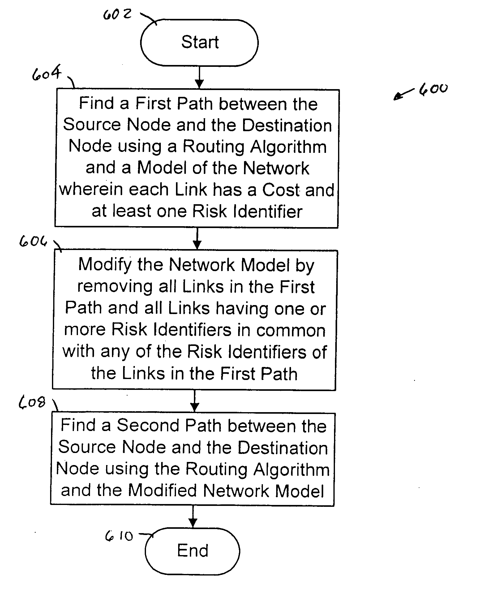
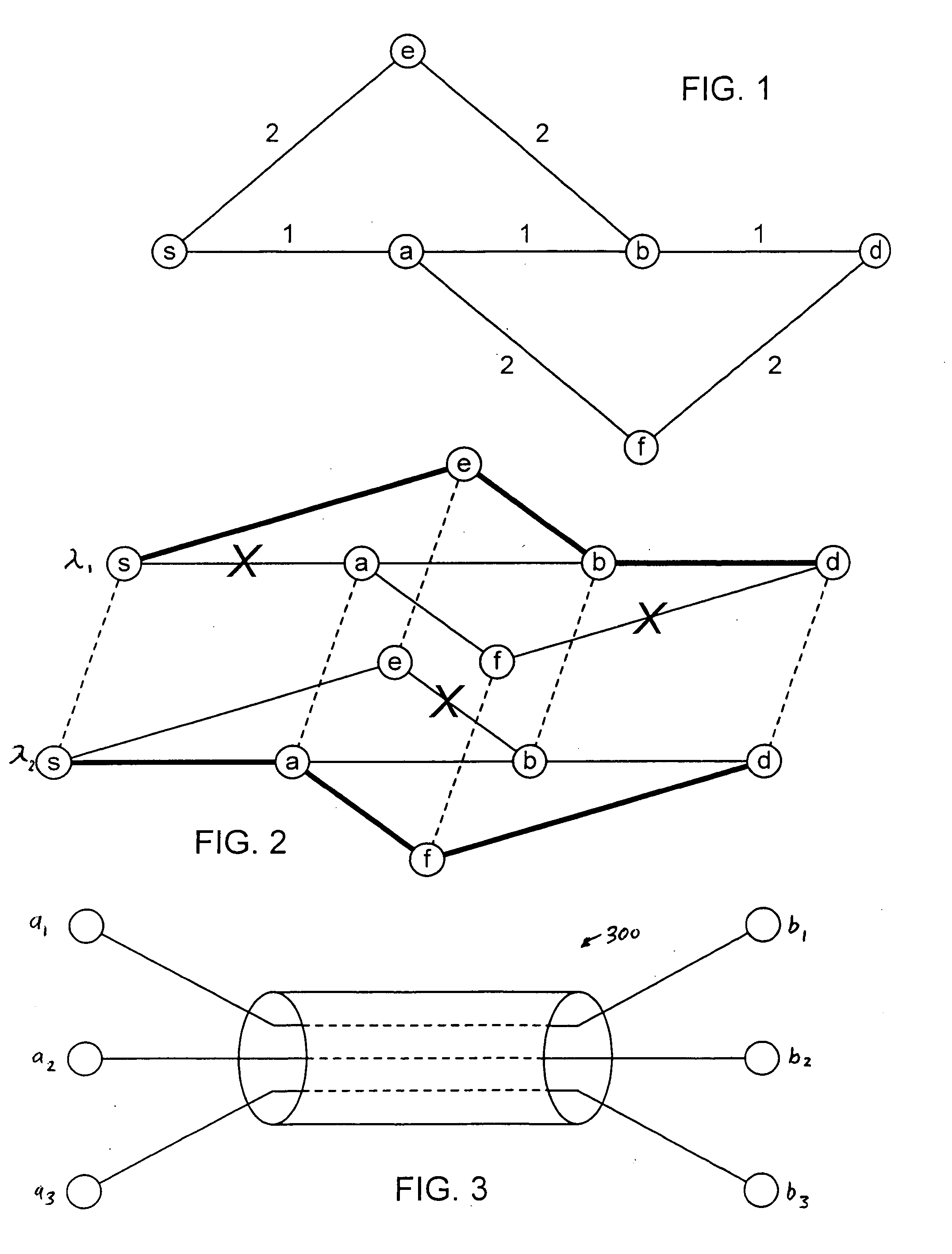
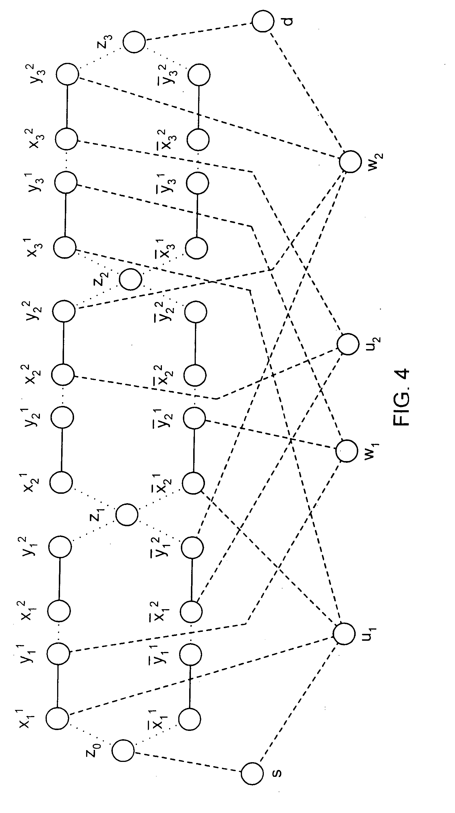
[0032] Path protection requires finding a working path and a protection path that are link disjoint. The present invention considers two problems on dynamic path protection in WDM mesh networks. In the first problem, a network without wavelength converters is considered; thus both the working path and protection path are subject to the wavelength continuity constraint. Existing polynomia...


PUM


Abstract

The present invention provides a system, method and apparatus for dynamic path protection in networks by finding two paths between a source node and a destination node in a network having multiple nodes and multiple links. A first path is found between the source node and the destination node using a routing algorithm and a model of the network. Each link has a cost and at least one risk identifier. The cost of the links having one or more risk identifiers that occur more than once in the network model are increased. The model is modified by removing all links in the first path and all links having one or more risk identifiers in common with any of the risk identifiers of the links in the first path. The second path is found between the source node and the destination node using the routing algorithm and the modified model.

Description

FIELD OF THE INVENTION [0001] The present invention relates generally to the field of communications and, more particularly, to a system, method and apparatus for dynamic path protection in networks. BACKGROUND OF THE INVENTION [0002] The rapid growth of the Internet and the World Wide Web are demanding more bandwidth from network carriers, pushing them to deploy high speed networks that use wavelength division multiplexing (“WDM”). A wavelength routed WDM network enables end users to communicate with one another via all-optical WDM channels that may span multiple nodes and fiber links. Such all-optical channels are referred to as lightpaths. [0003] Once an end-to-end path is established, a node or a fiber link failure may lead to the failure of all lightpaths that traverse that failed node or fiber link. Since the aggregate data rate on a single WDM fiber link can be as high as 50 Tbps, a failure may potentially lead to the loss of a large amount of data. To minimize the data loss,...

Claims


Application Information

Patent Timeline
Patent Type & Authority Applications(United States)
IPC IPC(8): H04J1/16H04J3/14H04J14/02H04L1/00H04L12/26H04L12/28H04L12/56
CPCH04J3/14H04J14/0227H04J14/0283H04J14/0284H04J14/0241H04L45/00H04L45/124H04L45/22H04L45/28H04J14/0291
Inventor YUAN, SHENGLIJUE, JASON P.
Owner BOARD OF RGT THE UNIV OF TEXAS SYST
Why Eureka
Try Eureka