

Application integration system and method using intelligent agents for integrating information access over extended networks
a technology of information access and intelligent agents, applied in the field of application integration systems and methods using intelligent agents, can solve the problems of reducing multiplicity also reduces efficiency and a company's operational economies of scale, and the cost and inconvenience of upgrading all of these components into one easy-to-use computer system is also enormous
- Summary
- Abstract
- Description
- Claims
- Application Information
AI Technical Summary
Benefits of technology
Problems solved by technology
Method used
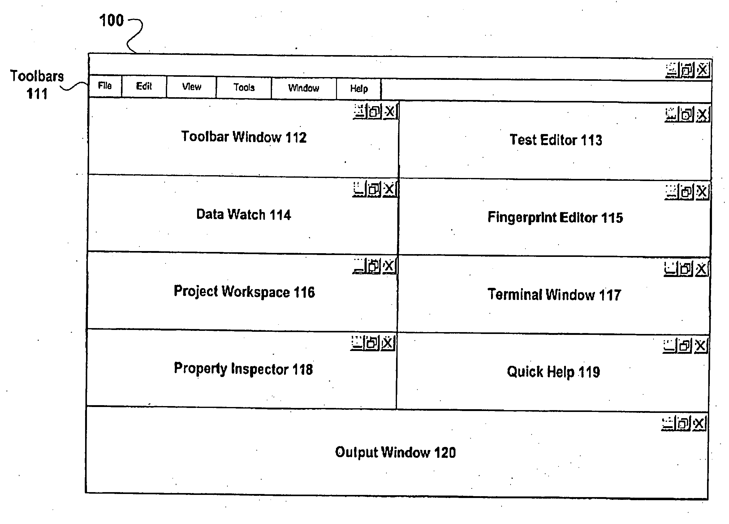
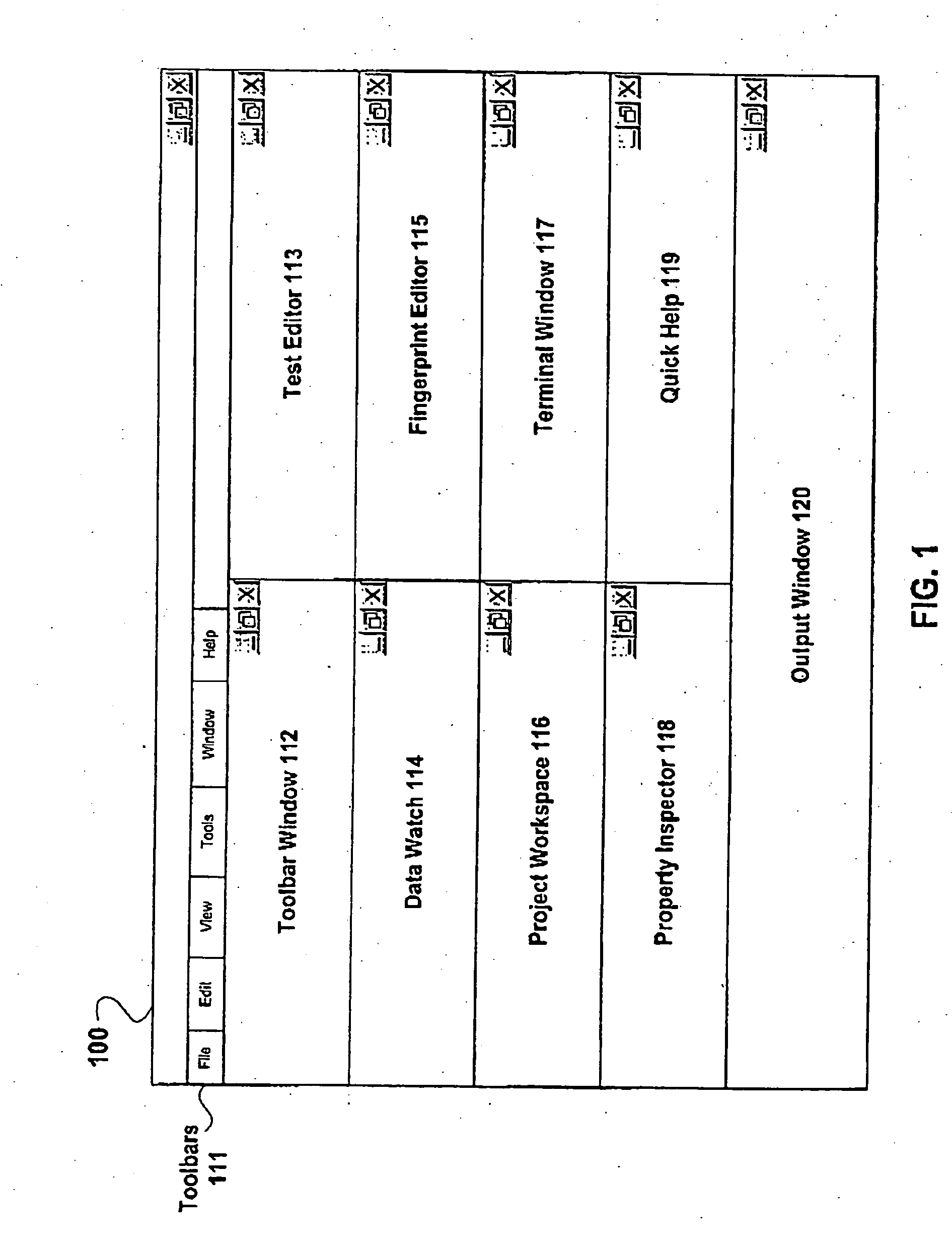
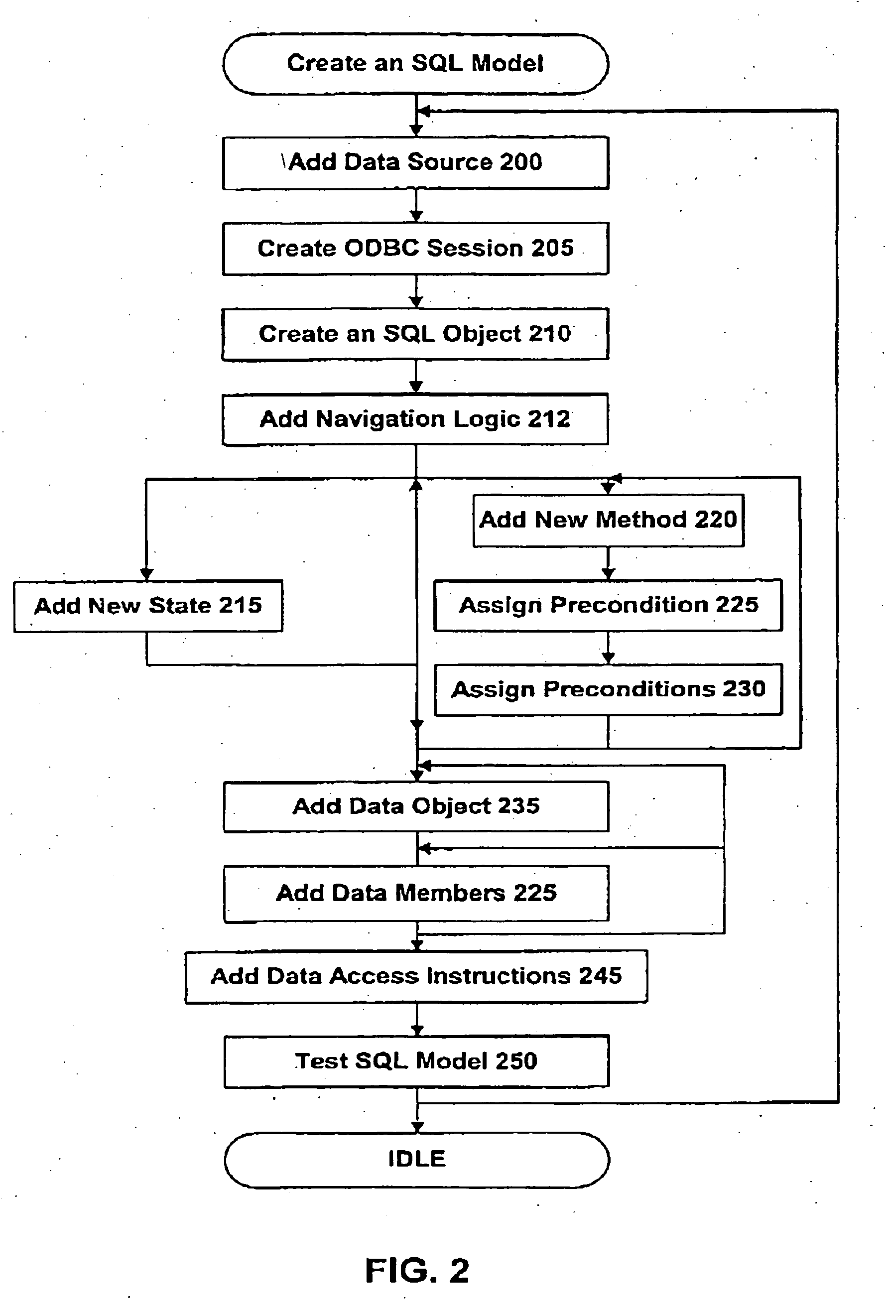
Image

Examples
example 1
InvoiceDisputesGenerated AND SendDisputesEmail_LOOP
Here, the reference to SendDisputesEmail_LOOP effectively means ‘Do While SendDisputesEmail LOOP is true’. Note that we can just as easily create a loop with a negative condition:
example 2
ReadyToReadInvoices AND !EndOfInvoiceList_LOOP
In this case, the loop we are creating is ‘Do While EndOfInvoiceList_LOOP is false’.
The model builder specifies the end point of the loop by referencing the same Loop State in the Postcondition state expression of a method. For example:
example 3
EmailSent AND !SendDisputesEmail_LOOP
EXAMPLE 4
InvoicesRead AND EndOfInvoiceList _LOOP
Note that the expected value of the Loop Stateshere is the opposite of what it was at the begin point. If the loop condition was ‘Do While SendDisputesEmail_LOOP is true’, then the loop is done when SendDisputesEmail_LOOP is no longer true.
The above described navigator uses the Loop State Stack to keep track of which loops it is in, when to reiterate, and where to start reiterating from. Each record in the Stack describes either the beginning or end point of one loop. It specifies the Loop State used to create the loop, the expected value of that state, the method that referenced the state, and where in the plan that method appears. Records are created and pushed onto the Stack when Loop States are encountered during the evaluation of the Pre- and Postconditions of methods.
The Stack Records mark loop begin points. Referencing a Loop State in a Precondition is not enough by itself to guaran...
PUM
 Abstract
Description
Claims
Application Information