Cutting method for plate glass mother material

a technology of mother material and cutting method, which is applied in the direction of thin material processing, metal-working equipment, manufacturing tools, etc., can solve the problems of large-scale manufacturing device, increased manufacturing cost, and inconvenient method for small-scale production of a wide variety of products

Inactive Publication Date: 2002-06-11
HOYA CORP
View PDF13 Cites 100 Cited by
  • Summary
  • Abstract
  • Description
  • Claims
  • Application Information

AI Technical Summary

Problems solved by technology

Moreover, problems are that a manufacture device is large-scaled and expensive, and that manufacture cost is raised.
According to this method, the pressed material has a high weight precision, but the method is not suitable for the production of a small amount of a wide variety of products.
This method is not suitable for the production of a large amount of a small variety of products, but is suitable for the production of the small amount of the wide variety of products.
In the reheat press method, when the weight of the material to be pressed is insufficient as compared with a cavity in the press molding die, the cavity of the molding die is insufficiently filled with the material to be pressed, which causes an elongation defect.
Moreover, when the material to be pressed has an excessive weight, another problem occurs that the material overflows the molding die.
Therefore, in the reheat press method, the weight adjustment of the material to be pressed is a big problem.
The blade dicing method lacks economical property because a part of the glass mother material is necessarily lost as a cutting margin.
Moreover, since wear on a blade (cutting blade) is relatively excessive, the blade needs to be frequently replaced.
Furthermore, since the blade is deflected during cutting, it is difficult to cut a large number of materials to be pressed having the same size out of one glass mother material, and weight dispersion among the obtained materials to be pressed relatively becomes large.
As a result, manufacture cost is relatively raised.
Therefore, even when the same ultra-hard wheel cutter is used to perform scribing with a quantitatively determined pressing force, desirable cracks cannot constantly be formed.
Therefore, cut members cannot be obtained with good precision.
When the rising occurs, a problem arises that adjacent cut pieces strike each other and corners are chipped.
When the corners are chipped, the materials to be pressed uniform in weight cannot be formed.
Additionally, in worse cases, the cut pieces jump to the outside, and another problem is that the operation cannot advance to the next process.
Therefore, when the materials to be pressed are obtained by the local compression cutting method, simply the cutting does not always suffice.
However, according to the inventors' researches, in many cases, even when the groove is formed in the position where the glass mother material can be divided into two equal parts, the glass mother material cannot be cut along the longitudinal cross section passing through the groove.
Therefore, when the material is laid on the plane, rattling usually occurs.
(2) Usually, micro cracks are present in the surface of the optical glass mother material.
If the shape follow-up property of the auxiliary cutting member is too high, that is, if the auxiliary cutting member is too soft, it is difficult to generate the tensile stresses necessary for cutting the glass mother material on both sides of the groove used as the index when the local compression is applied to the glass mother material.
Here, when the place where the groove is formed largely deviates from the position where the glass mother material can be divided into two equal parts, and the local compression is applied to the glass mother material using the groove as the index, the difference in size of the tensile stresses generated on both sides of the groove is enlarged, and it becomes difficult to cut the glass mother material along the longitudinal cross section passing through the groove.
Therefore, depending on the size of the glass mother material and the size of the target material to be pressed in the stage where cutting by the local compression is not performed yet, to obtain a large number of materials to be pressed from one glass mother material, in the process a situation sometimes occurs in which the auxiliary cutting member formed of one type of material cannot satisfy the above-described shape follow-up property.

Method used


Image

  • Cutting method for plate glass mother material
  • Cutting method for plate glass mother material
  • Cutting method for plate glass mother material

Examples


example 1

(1) Preparation of Glass Mother Material

First, an optical glass plate of 85.times.85.times.8 mm (formed of FD8 (glass type name) manufactured by Hoya Corp.) was prepared. The optical glass plate has the size and weight corresponding to those of 100 materials to be pressed (each weight of 2.46 g) in which 0.05 g is included as a margin taken by barrel polishing.

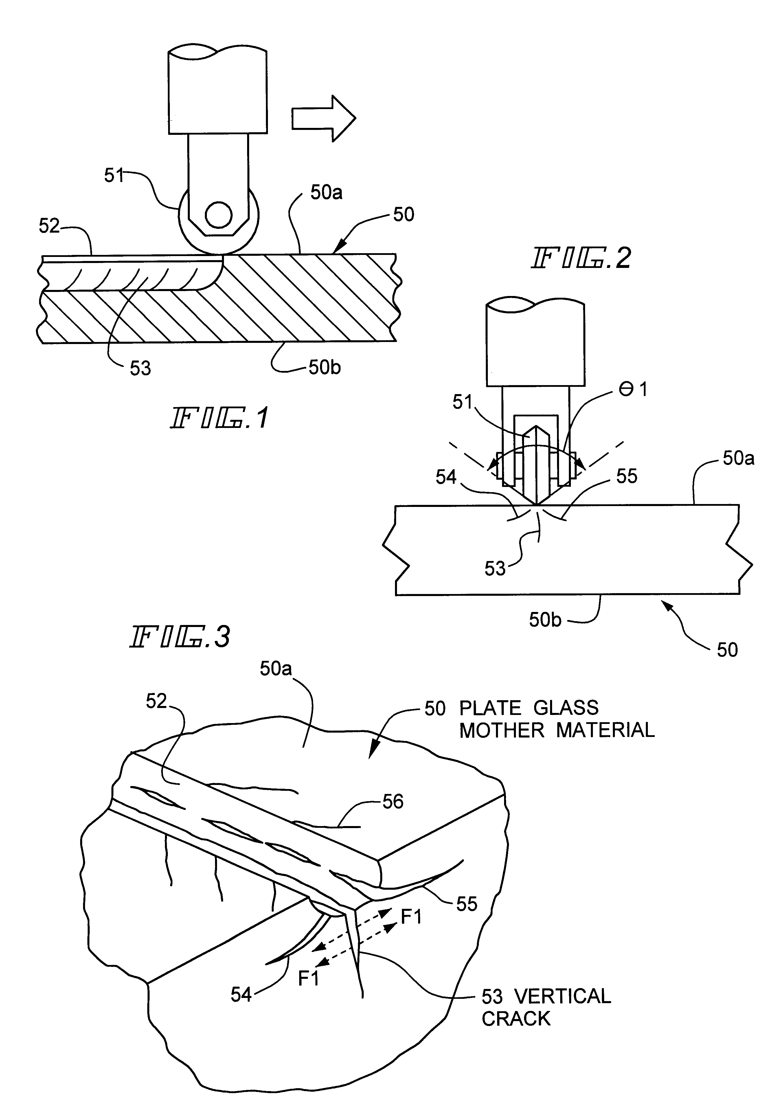
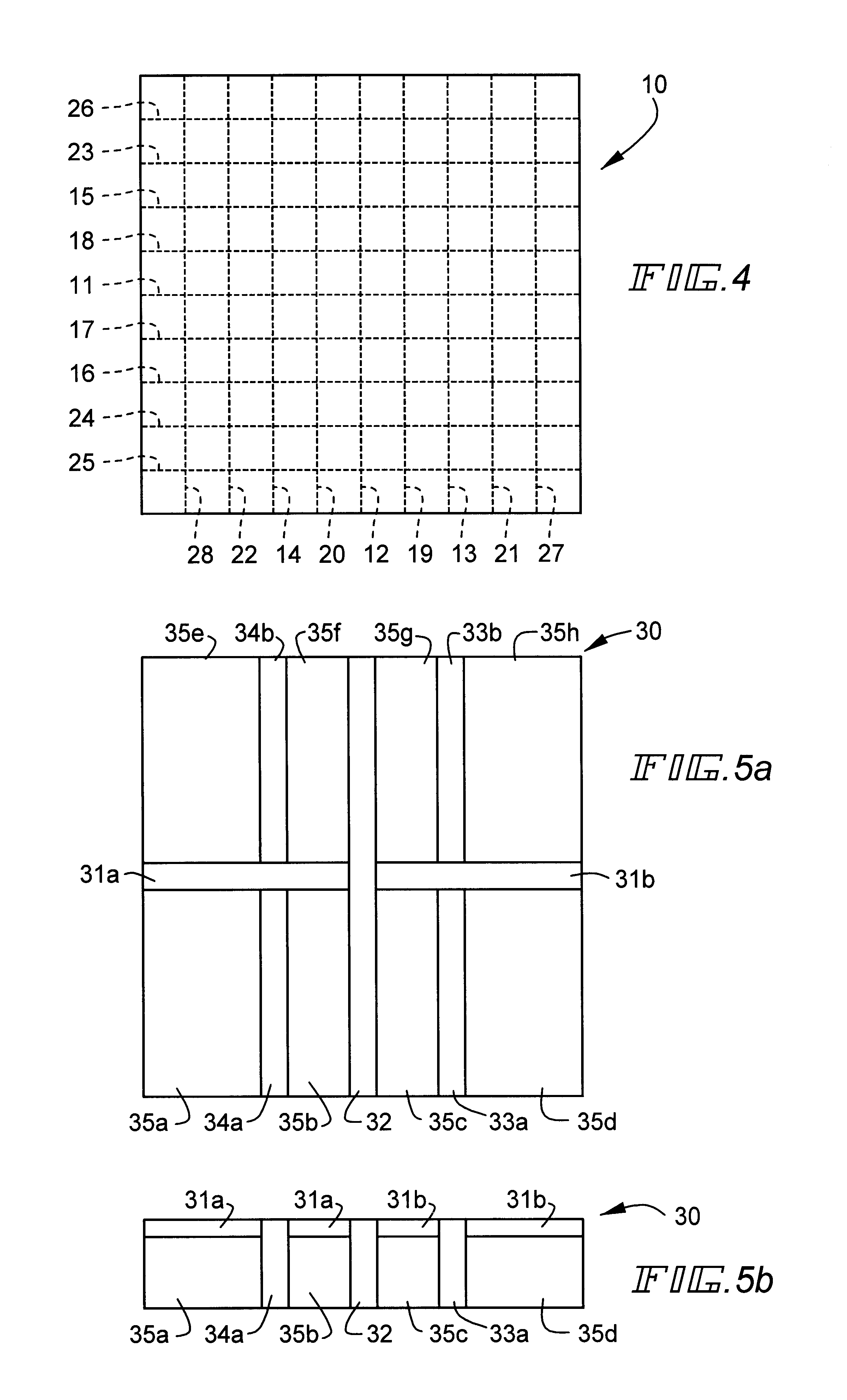
Subsequently, a wheel cutter having a blade portion formed of an ultra-hard material and having a blade tip angle of 130.degree. was used to form 18 grooves in total in one main surface of the optical glass plate, so that an optical glass mother material as a target was obtained. In this case, a load of 5 kgf was applied to the wheel cutter, and the grooves were formed in a lattice shape so that the materials to be pressed uniform in size can be obtained by 100 pieces in total from the optical glass mother material. The linear width of each groove is 1.2 mm, and the depth is 0.2 mm.

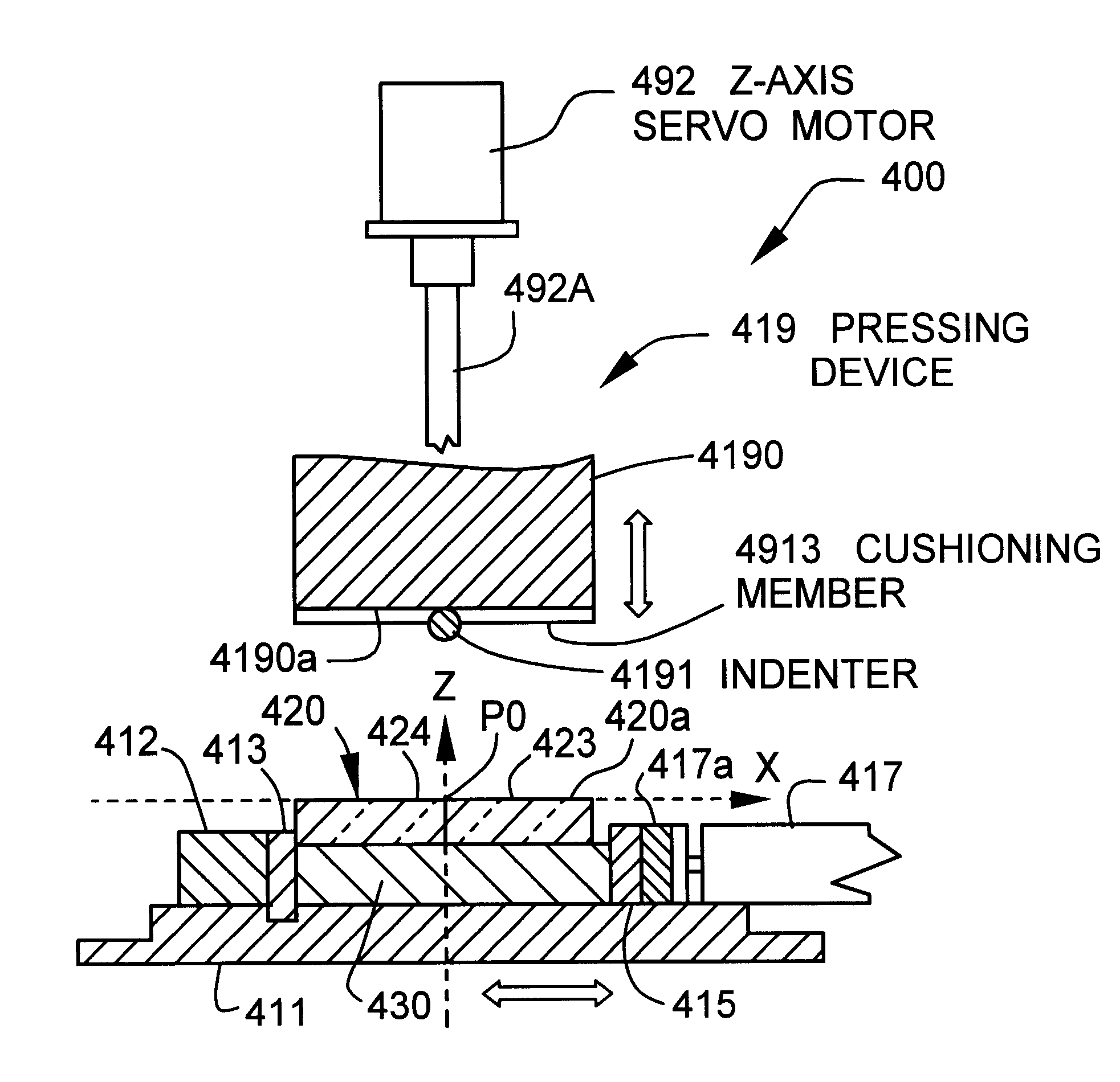
(2) Manufacture of Materials to be Pressed

Fir...

example 2

The optical glass mother material having a rattling degree of 0.35 mm was obtained in the same procedure as in Example 1 (1) except that as the material of the optical glass mother material, an optical glass plate of 85.times.85.times.8 mm (formed of BSC7 (glass type name) manufactured by Hoya Corp.), and 100 materials to be pressed in total were obtained from the optical glass mother material in the same procedure as in Example 1 (2).

For the materials to be pressed obtained in this manner, the measured weight ranges and dispersions of measured weights to theoretical weights were obtained. Results are shown with the theoretical weights in Table 2.

example 3

The optical glass mother material having a rattling degree of 0.35 mm was obtained in the same procedure as in Example 1 (1) except that as the material of the optical glass mother material, an optical glass plate of 85.times.85.times.8 mm (formed of NBFD11 (glass type name) manufactured by Hoya Corp.), and 100 materials to be pressed in total were obtained from the optical glass mother material in the same procedure as in Example 1 (2).

For the materials to be pressed obtained in this manner, the measured weight ranges and dispersions of measured weights to theoretical weights were obtained. Results are shown with the theoretical weights in Table 2.

As shown in Table 2, each of the materials to be pressed obtained in Examples 1 to 3 had a small dispersion of the measured weights to the theoretical weight, that is, a high weight precision.


PUM

PropertyMeasurementUnit
sizeaaaaaaaaaa
widthaaaaaaaaaa
thicknessaaaaaaaaaa

Abstract

The present invention is directed to a method of cutting glass mother material involving preparing the plate glass mother material in which a plurality of grooves are scribed, disposing the plate glass mother material with the grooves turned inward; and pressing an outer surface of the plate glass mother material with a cushioning member having a thickness not to be protruded downward from a lowermost portion of an indenter, with the cushioning member being attached onto an under surface of an indenter base excluding the indenter, pressing a portion opposite to the groove on the outer surface with the indenter having a stretched shape, and cutting the plate glass mother material.

Description

This application claims the Paris convention priority of Japanese patent application Hei 10-261347 filed on Sep. 16, 1998, the entire disclosure of which is incorporated herein by reference.1. Field of the InventionThe present invention relates to a method of cutting a plate glass member as a mother material of materials to be pressed for use on a reheat press method, and to a plate glass mother material cutting device, particularly to a method of cutting a plate glass mother material in which a plurality of grooves are scribed / processed beforehand on one main surface, and to a plate glass mother material cutting device.2. Description of the Related ArtWhen optical elements such as an optical lens and a prism are formed, press molding is used. Examples of a press molding method mainly include a precision press molding method, a direct press method, and a reheat press method.The precision press molding method is a molding method of transferring the shape and surface precision of a mo...

Claims


Application Information

Patent Timeline
Patent Type & Authority Patents(United States)
IPC IPC(8): C03B33/00C03B33/033C03B33/02
CPCC03B33/033Y10T225/12Y10T225/307Y10T225/325Y10T225/379Y02P40/57C03B33/02
Inventor YOSHIKUNI, KEISUKETSUKADA, SHOGO
Owner HOYA CORP
Why Eureka
Try Eureka