Method and arrangement for creating bevels on the edges of flat glass

a flat glass and edge technology, applied in the field of methods, can solve problems such as glass panel fracturing

Inactive Publication Date: 2015-03-19
LISEC AUSTRIA
View PDF7 Cites 60 Cited by
  • Summary
  • Abstract
  • Description
  • Claims
  • Application Information

AI Technical Summary

Benefits of technology

[0014]With the method according to the invention and the arrangement according to the invention, it is avoided that chipping occurs in laser-cut glass panels because of the extraordinarily sharp edges on the side when the glass panels are set up. This is also true

Problems solved by technology

Such chipping is disadvantageous, since it is a starting point for microcrac

Method used


Image

  • Method and arrangement for creating bevels on the edges of flat glass
  • Method and arrangement for creating bevels on the edges of flat glass
  • Method and arrangement for creating bevels on the edges of flat glass

Examples


Embodiment Construction

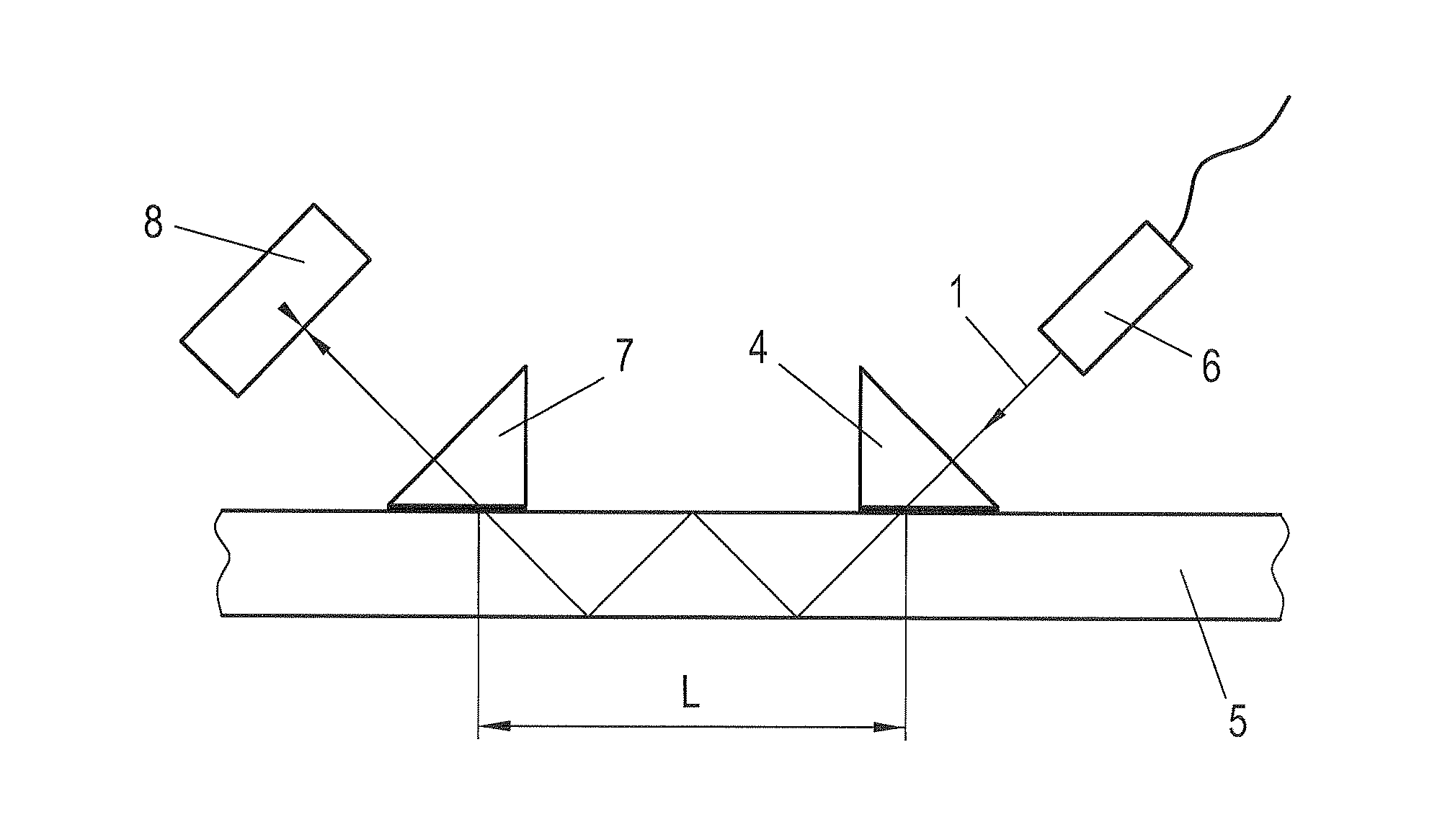
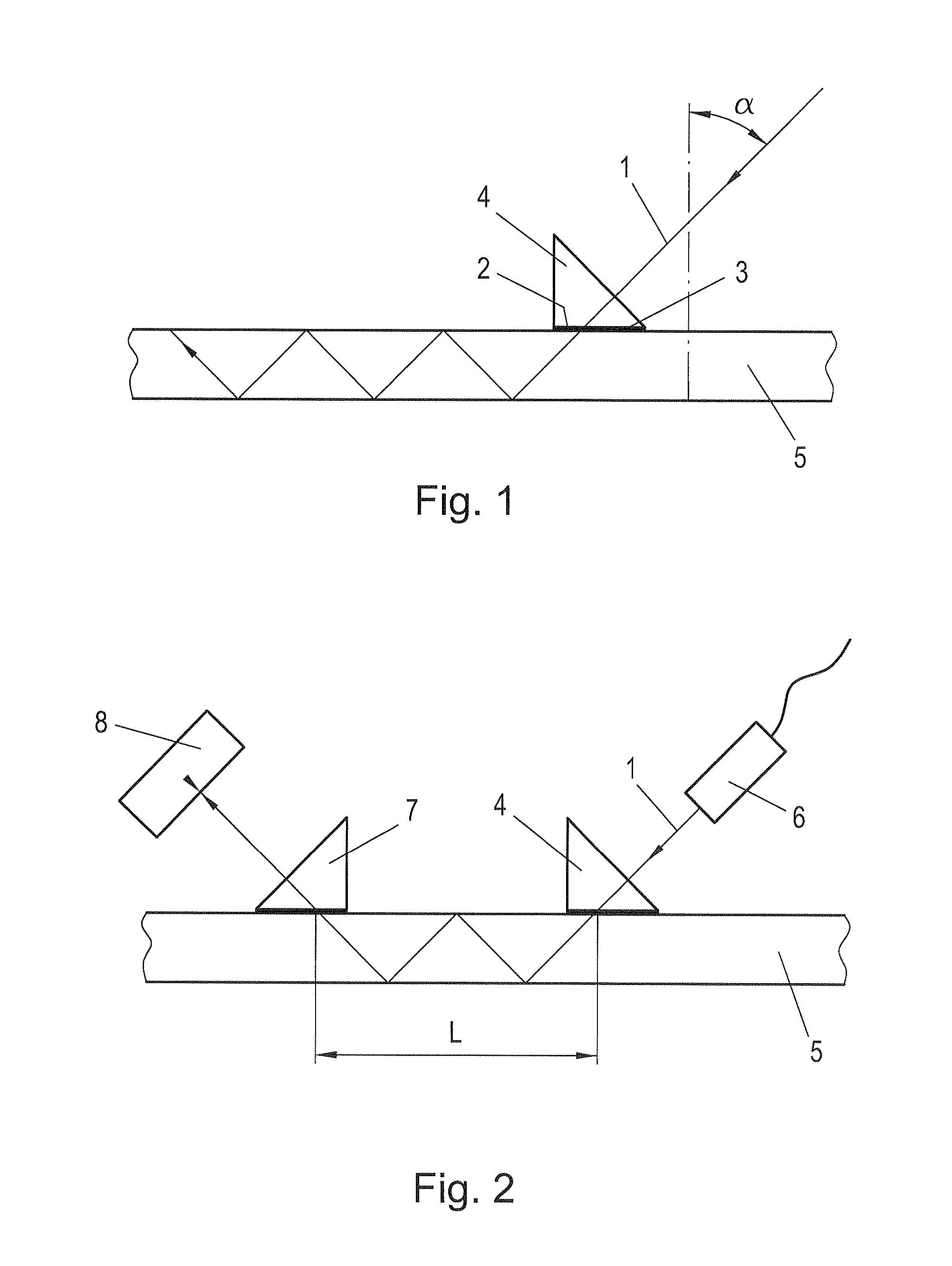
[0046]In the glass cutting shown in FIG. 1, using laser radiation with application of the effect of the total reflection of the laser beam on the second glass surface, a laser beam 1 strikes a prism 4, whereby the angle is close to 90°. The angle a between the normal surface of the glass 5 to be divided and the optical axis of the laser beam 1 is greater than or equal to the angle of the inside total reflection in the glass 5. In order to introduce the laser beam 1 from the prism 4 into the glass 5 to be divided, it is important that they be in optical contact. This is achieved in FIG. 1 in that in the area 2 between the prism 4 and the glass 5 to be divided, an optical contact is created, which is created by, for example, special liquids (water or glycerin) or (flexible) transparent (film-like) materials 3.

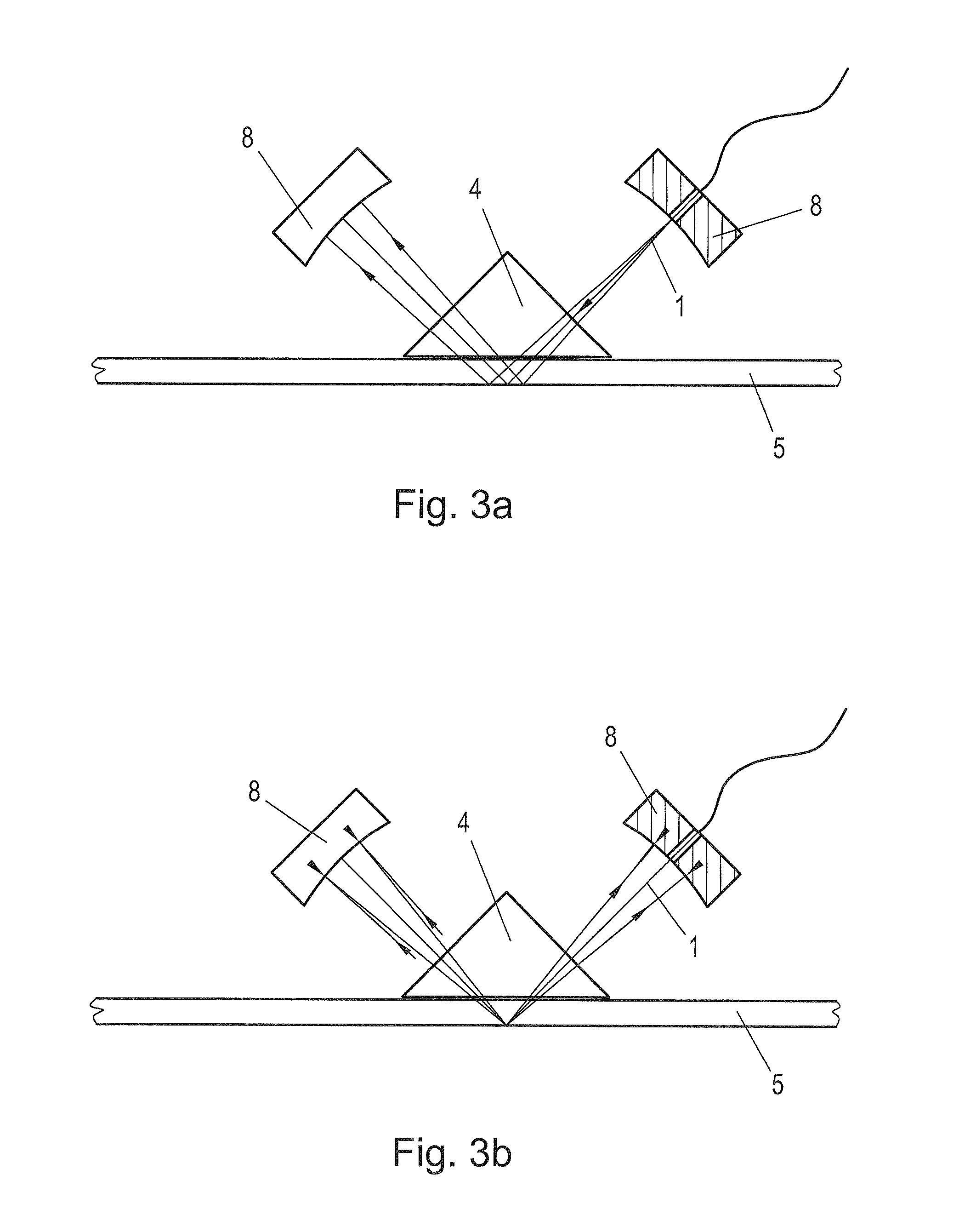
[0047]Within the scope of the invention, it can be provided that the sides of the prism 4 have complex geometric shapes, so that they produce hot spots with specific shapes (cf. ...


PUM

PropertyMeasurementUnit
Lengthaaaaaaaaaa
Lengthaaaaaaaaaa
Areaaaaaaaaaaa

Abstract

When dividing glass using laser radiation into blanks (5) made of glass, a bundled laser beam (1) is directed onto the glass to be divided, and while forming at least two blanks (5), the glass is divided with sides (15) lying in the area of the cut. After the glass is divided, a laser beam (1) is directed onto at least one edge (16) of a side (15) of the formed blank (5) in order to separate glass from the edge (16) while forming a bevel (17) that lies on the side (15). For forming the bevel (17), at least one laser source (6) and a reflector (19) assigned to the latter are moved along the side (15) so that the laser beam (1)—which with the plane of the blank (5) encompasses an acute angle—is effective for forming the bevel (17).

Description

FIELD OF THE INVENTION[0001]The invention relates to a method and a device with the features of the introductory parts of the independent claims that are directed toward the method, on the one hand, and toward the arrangement, on the other hand (EP 2 286 972 A).BACKGROUND OF THE INVENTION[0002]From AT 501 000 A1, a method and an arrangement for dividing glass, in particular flat glass, using laser radiation are known. With this known method, a bundled laser beam is directed onto the flat glass that is to be divided and reflected on a reflective surface arranged below the flat glass. The reflected laser beams are reflected again on the flat glass in the form of two bundles of laser beams, using a reflector that is arranged on the head of the laser and that has an opening for the bundled laser beams, in which reflector two cavity-like, elongated reflecting surfaces are provided. By the bundled laser beam, a microcrack is produced in the flat glass without heating the flat glass. The l...

Claims


Application Information

Patent Timeline
IPC IPC(8): B23K26/00C03B33/09B23K26/40
CPCB23K26/009C03B33/093C03B33/091B23K26/4075B23K26/40B23K2103/50C03B33/0222
Inventor MADER, LEOPOLD
Owner LISEC AUSTRIA
Why Eureka
Try Eureka