Methods of fabricating flat glass with low levels of warp

a flat glass and low level technology, applied in glass rolling apparatus, glass tempering apparatus, manufacturing tools, etc., can solve the problems of distortion in the display panel, one of the most troublesome and persistent problems, warping or ripple in the glass will have deleterious effects on the display quality, etc., to reduce the temperature of the glass, reduce the occurrence of s-warp, and reduce the temperature difference across the widths ws

Inactive Publication Date: 2007-03-22
CORNING INC
View PDF7 Cites 63 Cited by
  • Summary
  • Abstract
  • Description
  • Claims
  • Application Information

AI Technical Summary

Benefits of technology

[0028] (iv) the contacting of the edge rollers (27a, 27b) with the ribbon (15) locally reduces the temperature of the glass (for example, the edge rollers can be air or water cooled so that their steady state temperature is below that of the ribbon); and
[0029] (v) at least one location where the center line of the ribbon is at a temperature that is within the GTTR (e.g., a location within region 31 in FIG. 3), the first and second bead portions (21a, 21b) and / or the first and second S-warp portions (25a, 25b) of the ribbon (15) are heated, and / or the center portion of the ribbon is cooled, to reduce the temperature differences across the widths WS of the S-warp portions, and thereby reduce the occurrence of S-warp in the sheets.

Problems solved by technology

Any warping or ripple in the glass will have deleterious effects on the display quality.
This can result in distortion in the display panel.
It has been one of the most troublesome and persistent problems in the manufacture of LCD glass substrates.

Method used


Image

  • Methods of fabricating flat glass with low levels of warp
  • Methods of fabricating flat glass with low levels of warp
  • Methods of fabricating flat glass with low levels of warp

Examples


example

S-Warp Reduction

[0085]FIG. 4 shows a temperature profile in the glass transition temperature range (GTTR) for Corning Incorporated's Code Eagle 2000 glass that has been found to produce glass substrates with low levels of S-warp. More particularly, the temperature profile of FIG. 4 is used in at least the lower temperature portion of the GTTR.

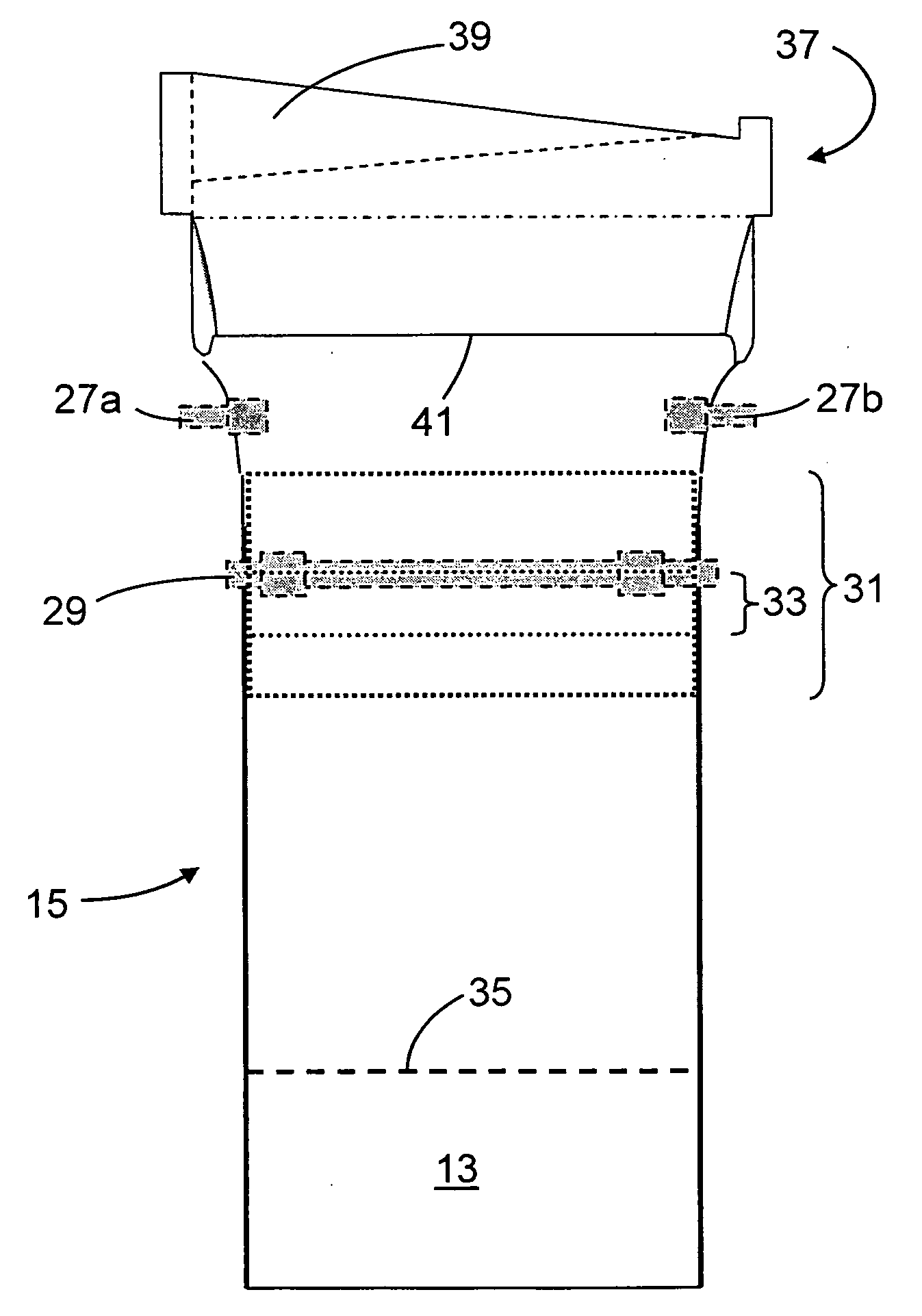
[0086] The figure shows both the temperature profile used to reduce S-warp and the corresponding ribbon thickness. The locations of the bead portions and the S-warp portions of the ribbon are also shown in this figure.

[0087] As can be seen from this figure, the temperature differences across the S-warp portions are each less than 40° C. In practice, keeping the temperature differences across the S-warp portions of the ribbon at this level or less has been found to result in low levels of S-warp, e.g., levels of 250 microns or less, while still allowing sufficient cooling of the ribbon by the edge rollers to permit the drawing of wide ribbons...


PUM

PropertyMeasurementUnit
temperatureaaaaaaaaaa

Abstract

A method of fabricating glass sheets (13) is provided in which the sheets are cut from a glass ribbon (15) composed of a glass having a glass transition temperature range (GTTR). The ribbon (15) is formed by a drawing process in which edge rollers (27a,27b) contact the glass ribbon (15) at a location along the length of the ribbon where the temperature along the center line (17) of the ribbon (15) is above the GTTR. The edge rollers (27a,27b) locally cool the ribbon (15), and the cooling produces a sine wave type buckling (S-warp) along the edges of the glass sheets (13). The S-warp is reduced or eliminated by heating the bead portions (21a, 21b) of the ribbon (15) and/or portions of the ribbon (the S-warp portions 25a and 25b) which are located next to the bead portions (21a, 21b) and/or by cooling the center portion of the ribbon (15) at least one location along the length of the ribbon (15) where the temperature at the ribbon's center line (17) is within the GTTR.

Description

I. FIELD OF THE INVENTION [0001] This invention relates to the manufacture of glass sheets such as the glass sheets used as substrates in display devices such as liquid crystal displays (LCDs). More particularly, the invention relates to methods for reducing a problem known as “S-warp,” which occurs in the manufacture of such glass sheets by, for example, the fusion downdraw process. II. BACKGROUND OF THE INVENTION [0002] A. Display devices [0003] Display devices are used in a variety of applications. For example, thin film transistor liquid crystal displays (TFT-LCDs) are used in notebook computers, flat panel desktop monitors, LCD televisions, and Internet and communication devices, to name only a few. Some display devices such as TFT-LCD panels and organic light-emitting diode (OLED) panels are made directly on flat glass sheets. With many display devices, the glass used in the panels must be flat to within approximately 150 and approximately 250 micrometers over the surface of t...

Claims


Application Information

Patent Timeline
Patent Type & Authority Applications(United States)
IPC IPC(8): C03B13/00C03B25/00
CPCC03B18/22C03B17/067Y02P40/57C03B17/06
Inventor BLEVINS, JOHN DAVIDNOVAK, ROBERT A.SHAY, GEORGE CLINTON
Owner CORNING INC
Why Eureka
Try Eureka