Steering device for vehicle
a steering device and vehicle technology, applied in the direction of lifting devices, non-deflectable wheel steering, suspensions, etc., can solve the problems of extending the time needed for adjustment, affecting the travel of the vehicle, and changing the relationship between the toe angle and the position of the steering wheel, so as to achieve convenient adjustment
- Summary
- Abstract
- Description
- Claims
- Application Information
AI Technical Summary
Benefits of technology
Problems solved by technology
Method used
Image

Examples
first embodiment
the present invention will now be described with reference to FIGS. 1 to 5.
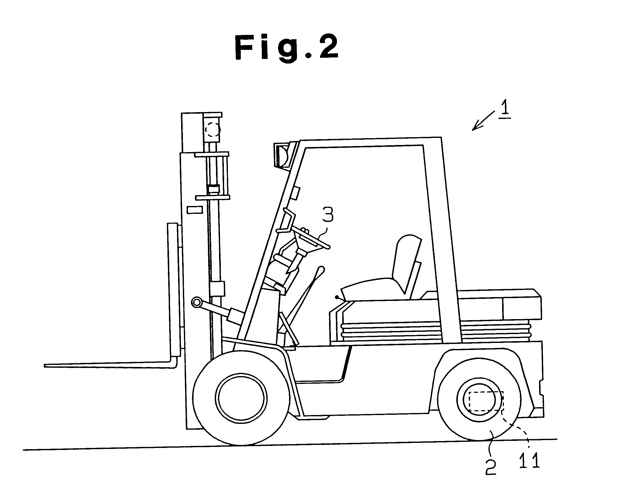
As shown in FIG. 2, an industrial vehicle, or forklift 1, has a pair of steered wheels, or rear wheels 2 (FIG. 2 only shows the left rear wheel 2). A steering device 11 steers the rear wheels 2 based on manipulation of a steering wheel 3.
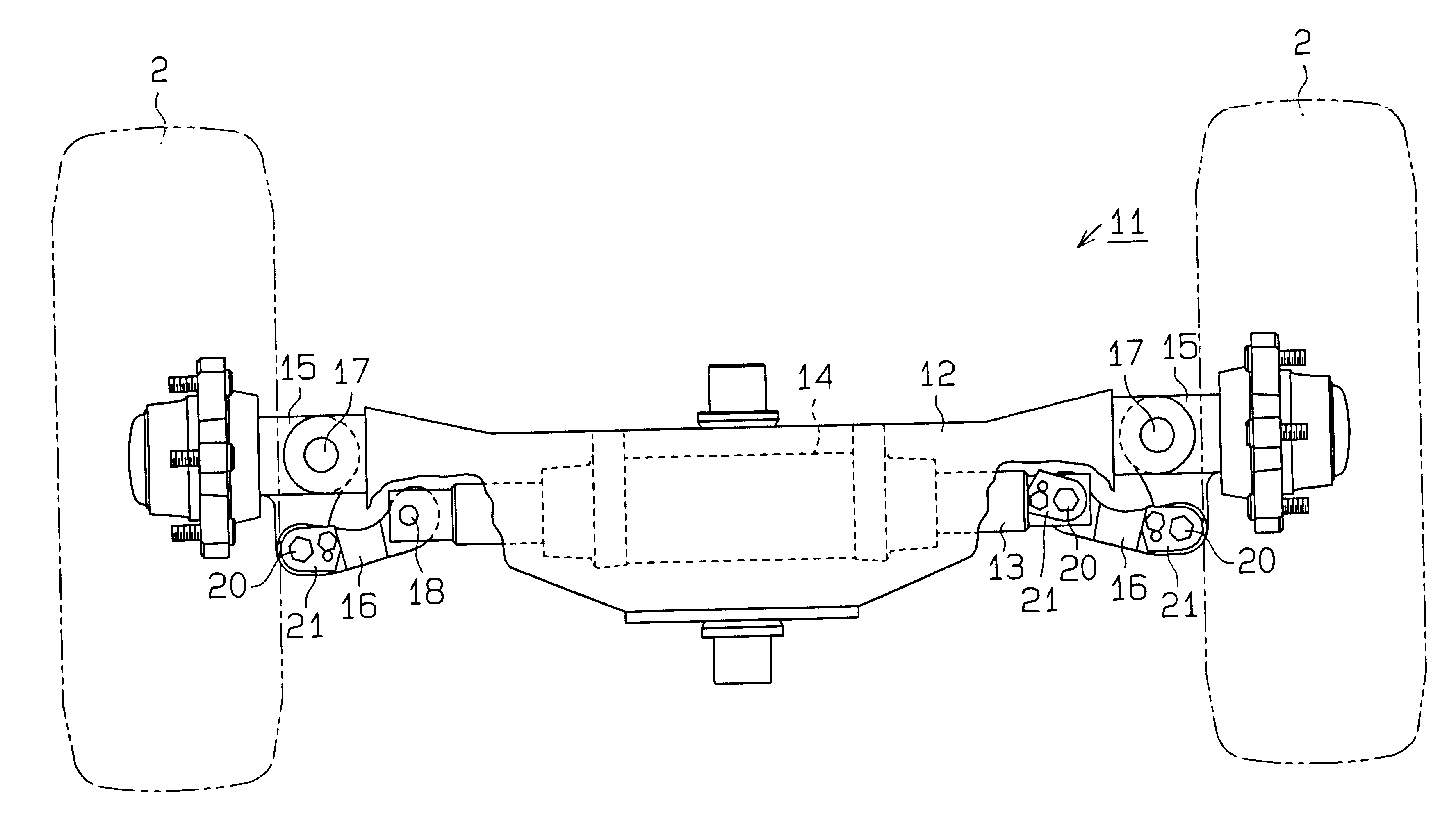
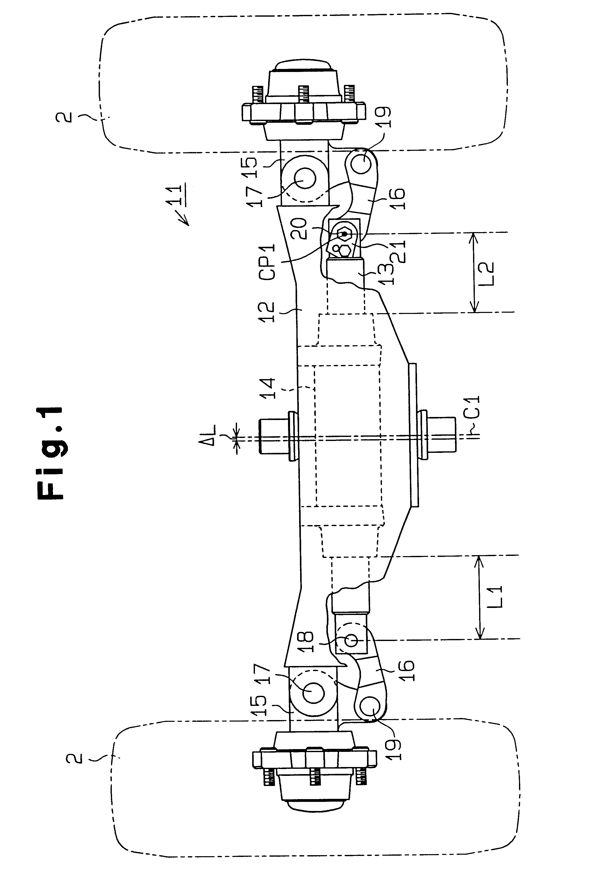
As shown in FIG. 1, the steering device 11 includes a cylinder 14 located in a rear axle 12. Each rear wheel 2 is supported by a knuckle arm 15. Each knuckle arm 15 is rotatably supported by a kingpin 17 at one end of the axle 12. Each rear wheel 2 and the corresponding knuckle arm 15 are integrally steered about the corresponding kingpin 17.
The cylinder 14 includes an actuator rod 13. The ends of the actuator rod 13 extend to the rear wheels 2. The knuckle arms 15 are coupled to the ends of the actuator rod 13 by tie-rods 16. The tie-rods 16 convert axial movement of the actuator rod 13 into pivoting of the knuckle arm 15 about the kingpins 17. In other words, as the actuato...
second embodiment
the present invention will now be described with reference to FIGS. 6 to 8. The differences from the embodiment of FIGS. 1-5 will mainly be discussed below, and like or the same reference numerals are given to those components that are like or the same as the corresponding components of the embodiment of FIGS. 1 to 5.
As shown in FIG. 6, two toe angle adjusting mechanisms, each including the adjuster pin 20 and the bracket 21, are located between the tie-rods 16 and the knuckle arms 15. Each end of the actuator rod 13 is coupled to the corresponding tie-rods 16 by a cylindrical support shaft 18.
FIG. 7 is a perspective view showing the toe angle adjusting mechanism between the right tie-rod 16 and the right knuckle arm 16. The left mechanism between the left tie-rod 16 and the left knuckle arm 15 has the same structure as the right mechanism of FIG. 7. As shown in FIG. 7, an upper through hole 51 and a threaded hole 52 are formed in the upper clevis arm 29 of the right tie-rod 16. A l...
PUM
 Abstract
Description
Claims
Application Information
 - Generate Ideas
- Intellectual Property
- Life Sciences
- Materials
- Tech Scout
- Unparalleled Data Quality
- Higher Quality Content
- 60% Fewer Hallucinations
Browse by: Latest US Patents, China's latest patents, Technical Efficacy Thesaurus, Application Domain, Technology Topic, Popular Technical Reports.
© 2025 PatSnap. All rights reserved.Legal|Privacy policy|Modern Slavery Act Transparency Statement|Sitemap|About US| Contact US: help@patsnap.com