Limited slip differential

a technology of differentials and limited slips, applied in the field of differentials, can solve the problems of increasing the risk of a motor vehicle having such a differential of becoming immobilized on substantially slippery surfaces, wheel hops and/or axle breaks, and the outer wheel rotating faster than the inner wheel

Inactive Publication Date: 2002-06-11
PERALTA MARK
View PDF31 Cites 29 Cited by
  • Summary
  • Abstract
  • Description
  • Claims
  • Application Information

AI Technical Summary

Problems solved by technology

However, when making either a left or right turn, the wheel on the outer end of the axle travels a greater distance than the wheel on the inner end of the axle, causing the outer wheel to rotate faster than the inner wheel.
This generally leads to twisting of the axle, and often results in wheel hop and / or axle breakage.
This condition increases the risk of a motor vehicle having such a differential of becoming immobilized on substantially slippery surfaces.
However, when the vehicle travels on ice, snow, or through mud, the differential speed between the left and right wheels increases substantially beyond the relatively small speed difference which occurs between the wheels on dry pavement.
In this instance "slip limitation" is desirable otherwise the vehicle may become immobilized.
On the other hand, slip limitation is not desirable in normal driving situations since slip limitation may adversely affect directional control of the vehicle and accelerate tire wear.
However, most of these limited slip differentials do not limit the speed difference between the driven wheels adequately at a substantially large speed differential or slip between the driven wheels.
Other limited slip differentials have valves, clutches, pistons or other special components that add to the complexity and cost of production.
There is a need for a limited slip differential, which limits the speed differentiation or "slip" between the driven wheels, and gradually increases torque to the non-slipping wheel, as the rotational speed difference between the slipping wheel and the non-slipping wheel increases.
However, none of the limited slip differentials adequately satisfies these aforementioned needs.
These limited slip differentials "bind" the wheels together, starting with a specified amount of torque, but increasing the slip limitation when the input torque increases.
U.S. Pat. No. 3,292,456 (Saari) and U.S. Pat. No. 3,738,192 (Belansky), and European Patent No. 130806A2 (Quaife) disclose parallel-axis differentials having pinions that are continuously meshed in a circumferential manner, which provide slip limitation, resulting from an increase in frictional surfaces at tooth meshing points and between pinions and casing.
Such limited slip differentials may be acceptable for driven wheels on dry pavement, but are not adequate on slippery surface.
These differentials produce increasing slip limitation, as the speed difference between the driven wheels increases.
However, although such low displacement designs result in low slip limiting capacity.
Although these differentials produce increasing slip limitation with increasing speed difference at the driven wheels, such devices are costly as a result pistons, cylinders, and spool valves required in the differential.
The fluid shearing resistance increases as the speed difference increases, thus resisting the "slip" between the two wheels with increasing force, as the speed difference between the two wheels increases; however, the maximum torque capacity of the viscous coupling is relatively small.
Additional increase in differential speed also increases pumping action, which further increases fluid pressure, leading to increase in torque transfer or slip limitation.
However, the construction of this limited-slip differential requires a pump, valves, cylinder, piston, seals, and clutches that add to the complexity and cost of the device.
Fluid pressure build-up caused by the pumping action results in pumping resistance, and, thus, slip limitation at the opposing output shafts of the limited slip differential, especially at high rotational speed differences between the opposing output shafts.

Method used


Image

  • Limited slip differential
  • Limited slip differential
  • Limited slip differential

Examples


Embodiment Construction

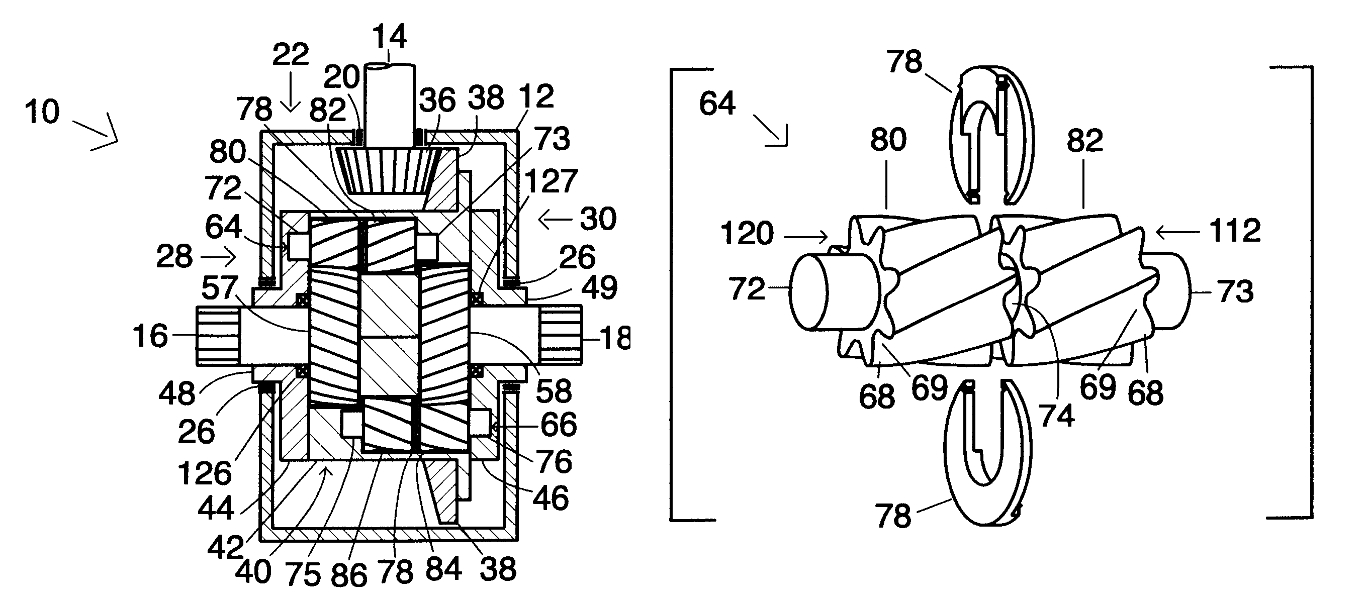
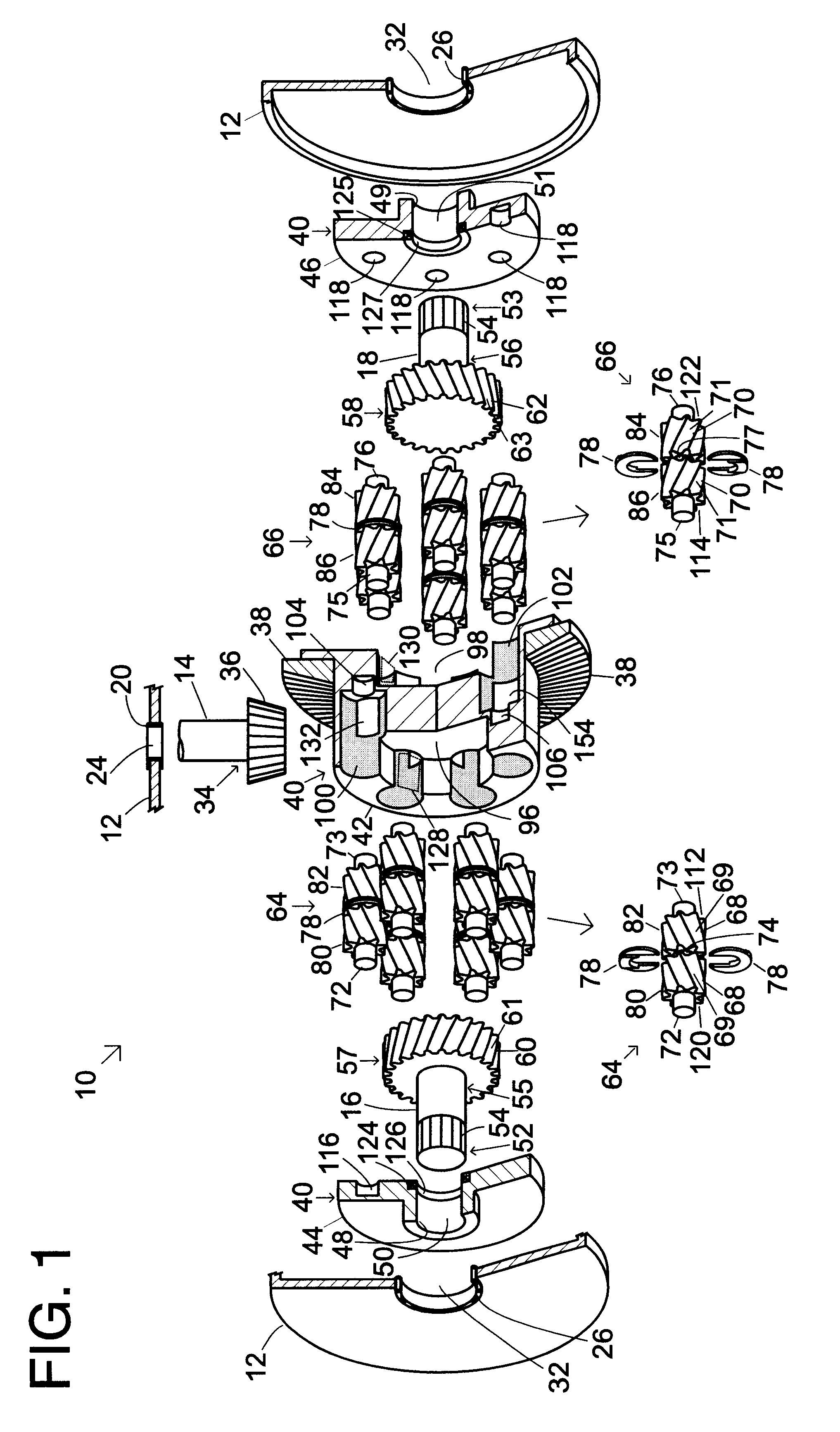
An alternative embodiment of a pinion 210 is shown in FIG. 19, which is substantially the same as the pinion 64 having the partitions 78, shown in FIGS. 11A, 11B, 12A, and 12B, except that the pinion 210 has a central hole 212 to accommodate a separate pinion shaft 214.

Another alternative embodiment of a pinion 216 is shown in FIG. 20, also having a separate shaft 218 and external splines 220 affixed thereto. The pinion 216 has a one-piece partition 222 and two separate substantially the same pinion sub units 224. Each pinion sub unit 224 has a central hole 226 and internal splines 228 affixed therethrough each of the pinion sub units 224. The internal splines 228 therethrough the pinion sub units 224 mate and interlock with the external splines 220 of the shaft 218.

An alternative embodiment of the limited slip differential 229 which is substantially the same as the limited slip differential 10 shown in FIGS. 1-20 is shown in FIG. 21, except that the limited slip differential 10 has...


PUM


Abstract

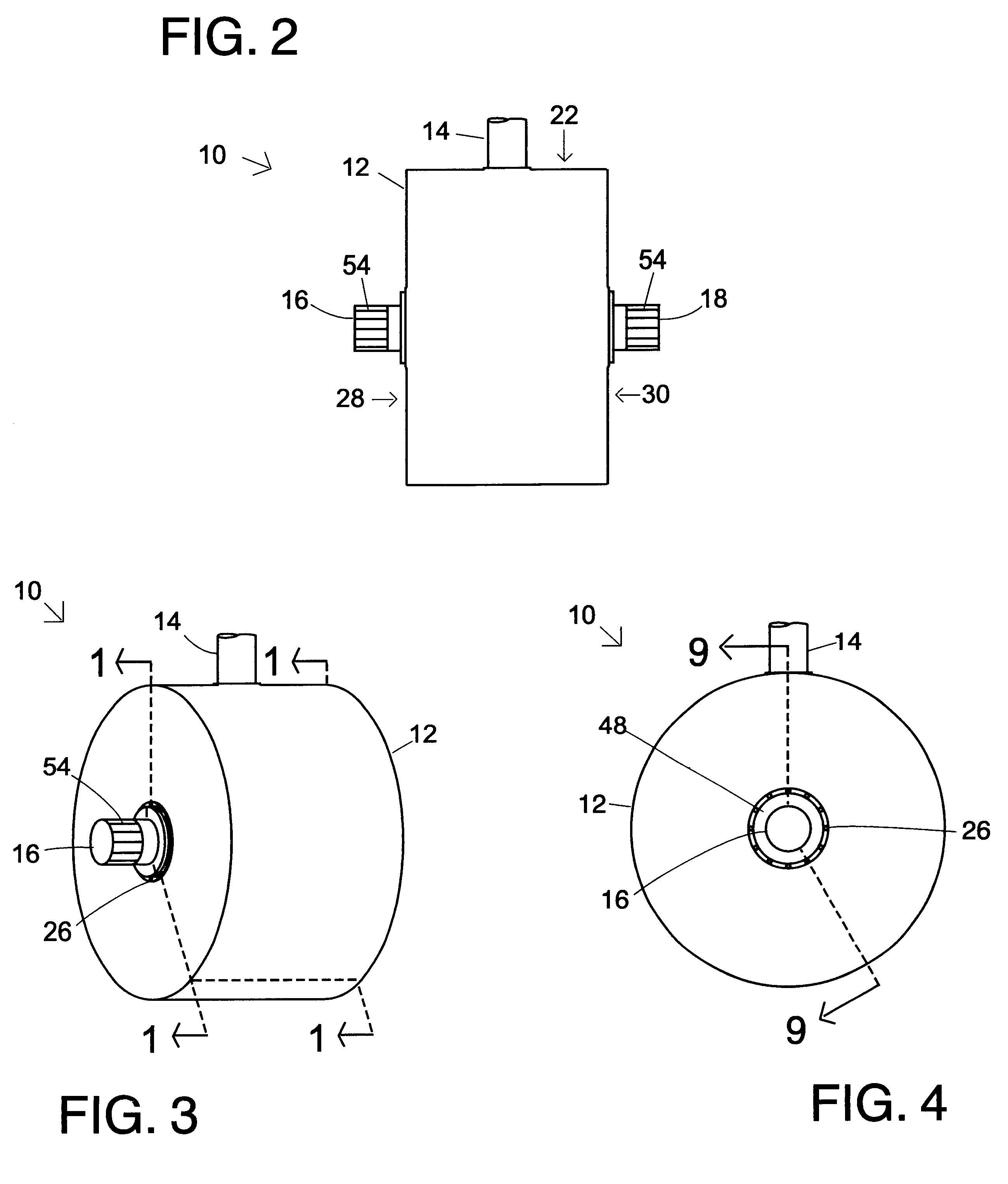
A limited slip differential comprising a casing containing a fluid medium, the casing rotatably driven along an axis by an input member; a plurality of opposing pinions therein the casing that are immersed in the casing fluid medium, having substantially parallel rotational axes, the opposing pinions meshing one with the other circumferentially at medial portions of the meshing opposing pinions; the pinions having partitions therebetween lateral and said medial portions of each of the opposing pinions; opposing driven gears, immersed in the casing fluid medium, the opposing driven gears meshing with a plurality of the lateral portions; the opposing driven gears having output shafts adjoined thereto; the casing having opposing holes therethrough, the opposing output shafts rotatably mounted therethrough; and seals adapted to retain said fluid medium therein said casing.

Description

1. Field of the InventionThe present invention relates generally to differentials and more particularly to limited-slip differentials.2. Background ArtAn axle with a wheel affixed to each end may be driven by a power source to propel a vehicle in a substantially straight line. However, when making either a left or right turn, the wheel on the outer end of the axle travels a greater distance than the wheel on the inner end of the axle, causing the outer wheel to rotate faster than the inner wheel. This generally leads to twisting of the axle, and often results in wheel hop and / or axle breakage.Differentials having a single input member, which drive two output members in a manner that permit the speeds of each of the output members to differ have been known. Differentials emerged from the need to have both output wheels of a driven axle to rotate at different speeds. Typical current day differentials still remain quite similar to the first known successful differential, invented in 18...

Claims


Application Information

Patent Timeline
Patent Type & Authority Patents(United States)
IPC IPC(8): F16H48/10F16H48/00F16H48/11F16H48/27F16H48/285
CPCF16H48/10F16H48/11F16H48/285F16H48/27F16H2048/106
Inventor PERALTA, MARK
Owner PERALTA MARK
Why Eureka
Try Eureka