Breaker device
- Summary
- Abstract
- Description
- Claims
- Application Information
AI Technical Summary
Problems solved by technology
Method used
Image
Examples
first embodiment
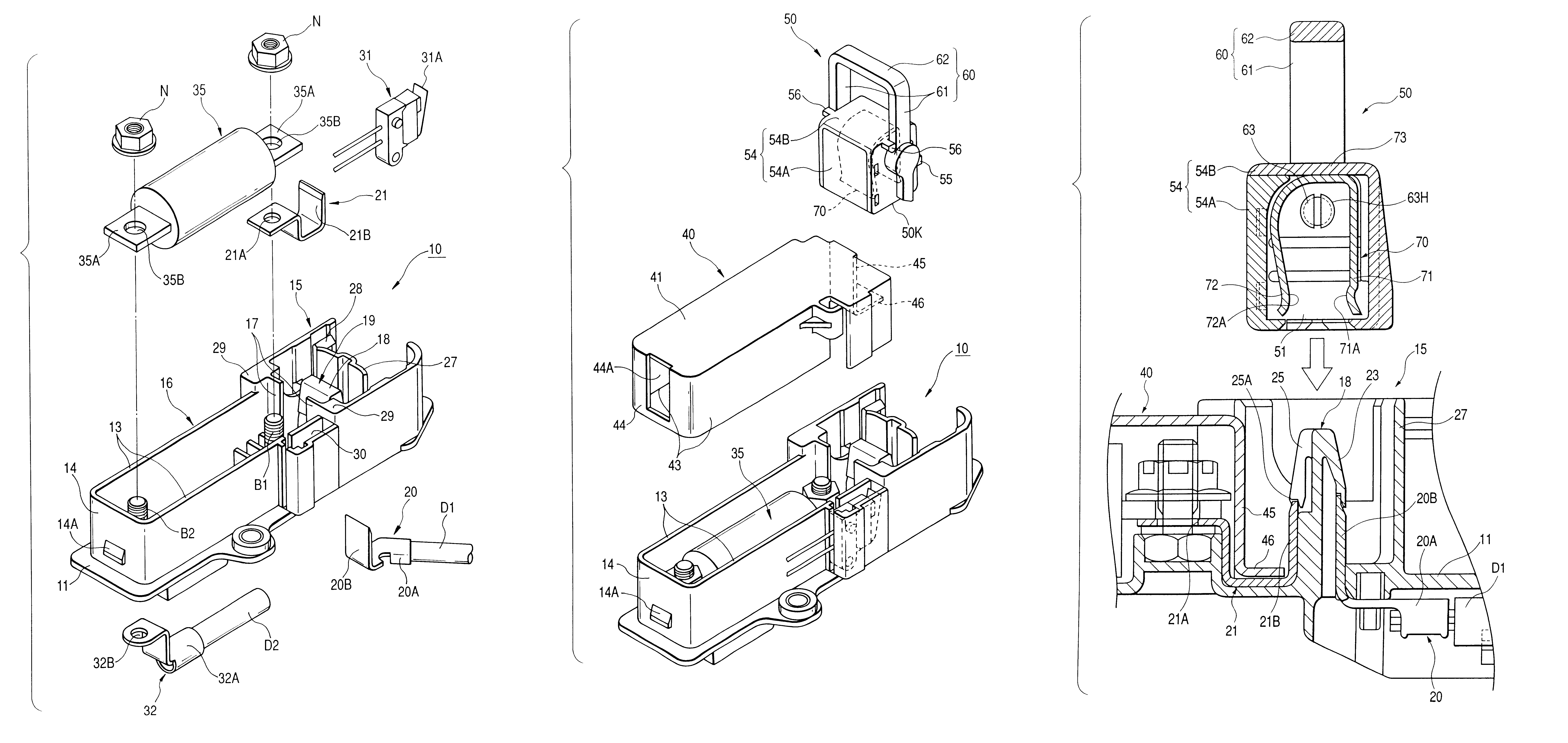
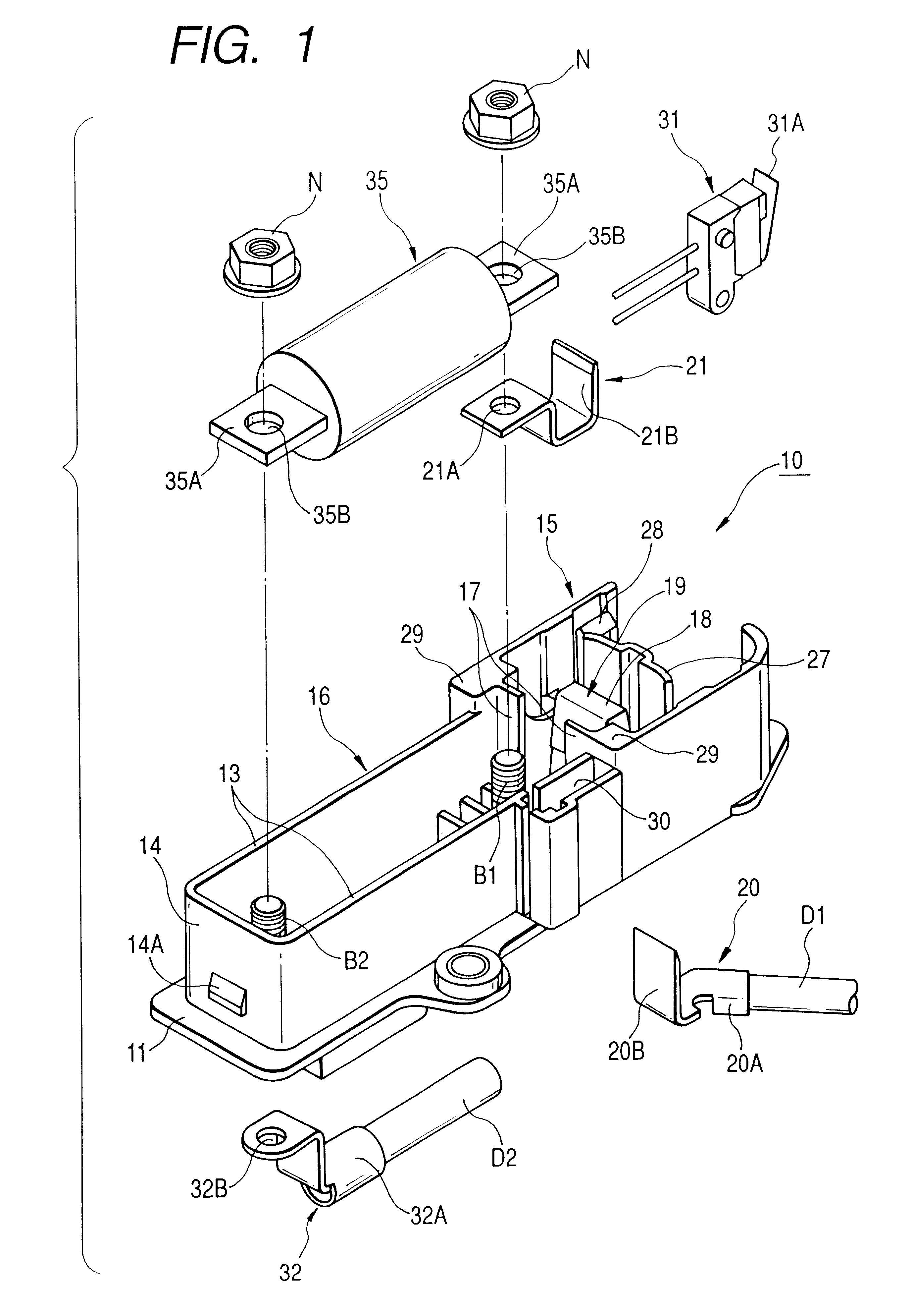
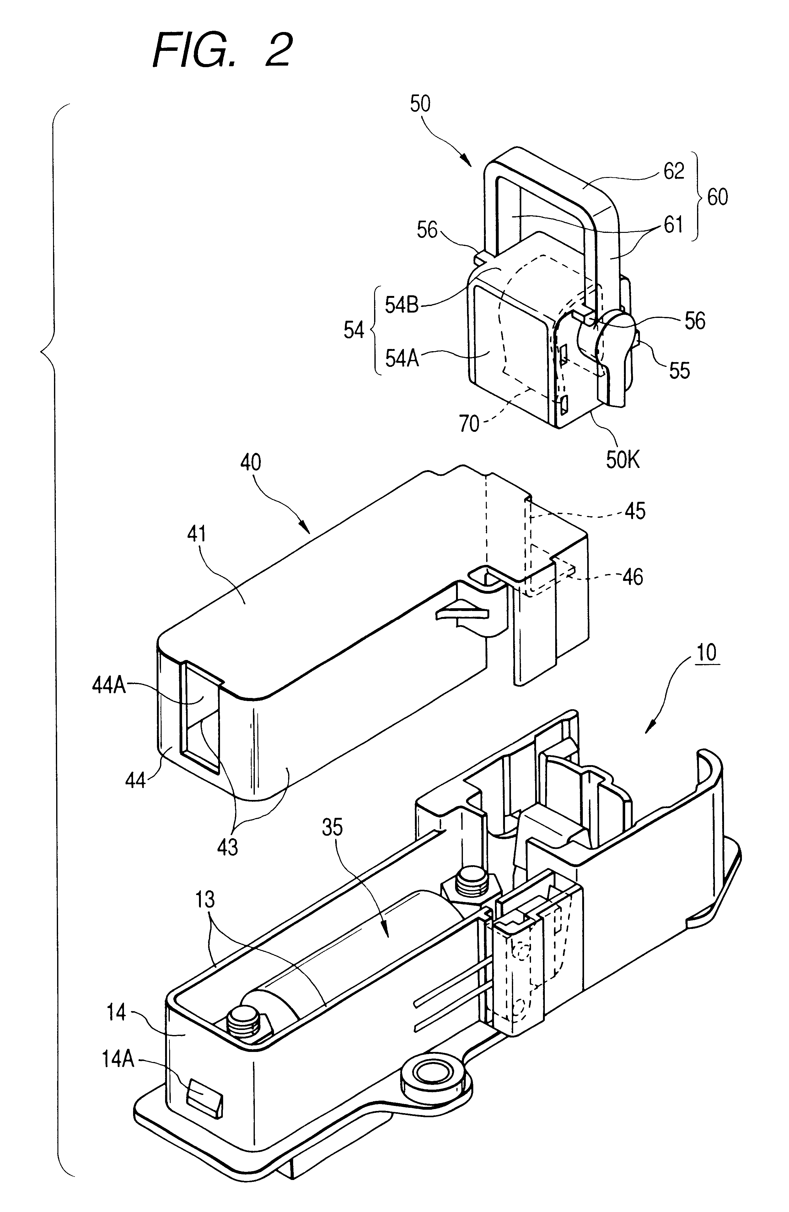
Referring to FIGS. 1 to 10B, an embodiment of the present invention will be explained as follows.
The breaker device of this embodiment is arranged in the middle of a power cable of an electric automobile and used for changing over the power cable between a state of continuity and a state of non-continuity.
As shown in FIG. 1, the shape of the breaker body 10 provided in this breaker device is formed in such a manner that a pair of long walls 13, 13 are extended in parallel with each other in the longitudinal direction of the flat-sheet-shaped base section 11, and these long walls 13, 13 are connected with each other at one end portion by the short wall 14 and open from each other at the other end portion. On the open side, an interval between the long walls 13, 13 is extended step-wise, and the plug accommodating section 15 is formed inside the long walls 13, 13, and further on the closed side, the fuse accommodating section 16 is formed which are surrounded by both the long walls 13...
second embodiment
The second embodiment of the invention will be described below.
The structures of the breaker device of this embodiment is the same as those of the breaker device described in the first Embodiment. The action of the breaker device will be explained below.
This breaker device is attached to an electric automobile in the following manner. A portion of the power cable of the electric automobile is attached to the breaker body 10 as electrical wires D1, D2, and the breaker body 10 is fixed at a predetermined position of the electric automobile when a bolt is inserted into the attaching hole 11A (shown in FIG. 5) formed in the base section 11.
Next, the cover 40 is attached to the fuse accommodating section 16 of the breaker body 10. The cover 40 is pressed so that the long wall 43 and the short wall 44 can be respectively engaged with the outside of the long wall 13 and the short wall 14 of the breaker body 10. When the cover 40 is pressed, the engaging hole 44A formed on the short wall 44...
third embodiment
A third Embodiment of the invention will be described below with reference to the drawings. The main feature of this embodiment is a pair of protection walls 26 as shown in FIGS. 6B and 11-15. The other structures are the same as those of the first embodiment.
As shown in FIGS. 6B, at the forward end side of the reverse face of the protruding wall 18, there are provided a pair of lances 25, 25 for preventing the second stationary electrode 21 from coming off. On both sides of the protruding wall 18, there are provided a pair of protection walls 26, 26 which are adjacent to the lances 25 and raised higher than the lances 25. These lances 25, 25 are formed into a cantilever-shape and rise from the forward end portion of the protruding wall 18 and extend downward in parallel with each other, and the forward end portion of the second stationary electrode 21 is butted against the lower face of the engaging section 25A provided in the lower end portion as shown in FIG. 11. As shown in FIG....
PUM
 Abstract
Description
Claims
Application Information
 - R&D
- Intellectual Property
- Life Sciences
- Materials
- Tech Scout
- Unparalleled Data Quality
- Higher Quality Content
- 60% Fewer Hallucinations
Browse by: Latest US Patents, China's latest patents, Technical Efficacy Thesaurus, Application Domain, Technology Topic, Popular Technical Reports.
© 2025 PatSnap. All rights reserved.Legal|Privacy policy|Modern Slavery Act Transparency Statement|Sitemap|About US| Contact US: help@patsnap.com


