
Apparatus and method of mounting and supporting a solar panel

a solar panel and solar panel technology, applied in the direction of heat collector mounting/support, lighting and heating apparatus, sustainable manufacturing/processing, etc., can solve the problems of wrought problems, affecting causing the installation of the solar panel to be unable to meet the requirements of the final field installation,

Inactive Publication Date: 2009-08-20
APPLIED MATERIALS INC
View PDF25 Cites 62 Cited by
  • Summary
  • Abstract
  • Description
  • Claims
  • Application Information

AI Technical Summary

Benefits of technology

[0063]The cross-sections of the lower transverse rail 1012, the upper transverse rail 1014, and the one or more middle transverse rails 1016 illustrated in FIGS. 12A and 12B are illustrative and not intended to be limiting to the scope of the invention discussed herein, since one skilled in the art would appreciate that the shape, cross-sectional area, and materials used to form them can be adjusted to provide a desired structural stiffness, provide a desired amount of support to the solar panel, reduce the mechanical stress induced in the solar panel from external sources (e.g., wind and thermal expansion), and / or achieve a desired cost target.

Problems solved by technology

However, many challenges remain in achieving this goal, such as efficient, low cost mounting of solar panels both in filed and rooftop environments.
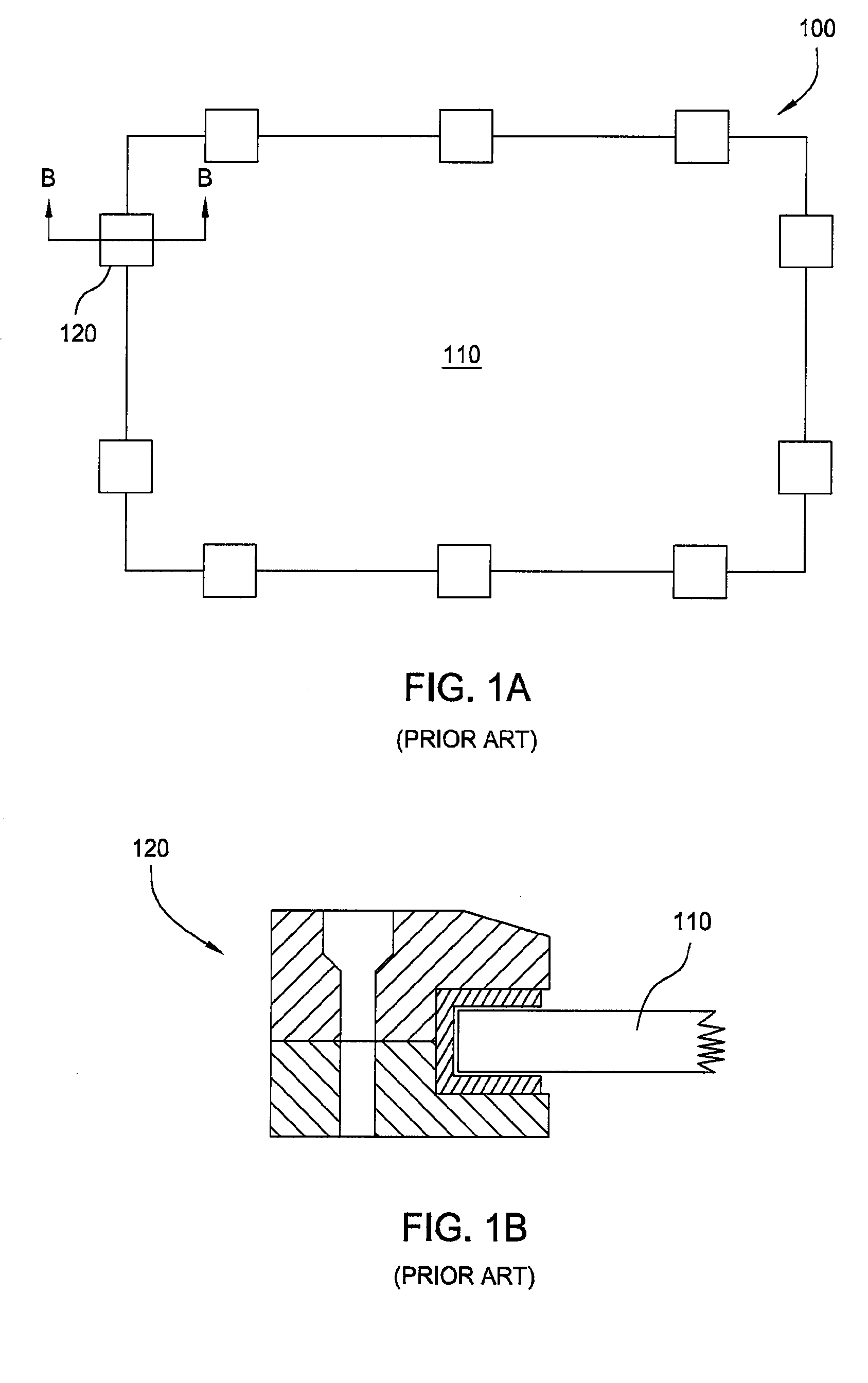
This configuration and mounting approach results in a bulky solar panel configuration while adding significant cost to the production of the panel as well as the ultimate field installation.
However, this approach is wrought with problems.
Thus, breakage of the solar panel 110 becomes a problem having significant repair / replacement expenses associated therewith.
Additionally, solar panels, by their very nature, are exposed to high temperature loading via exposure to solar radiation.
As a result, panels that are solely mounted by clamping at the perimeter may slip and shift out of position, which often results in improper orientation or breakage of the solar panel.

Method used


Image

  • Apparatus and method of mounting and supporting a solar panel
  • Apparatus and method of mounting and supporting a solar panel
  • Apparatus and method of mounting and supporting a solar panel

Examples


Embodiment Construction

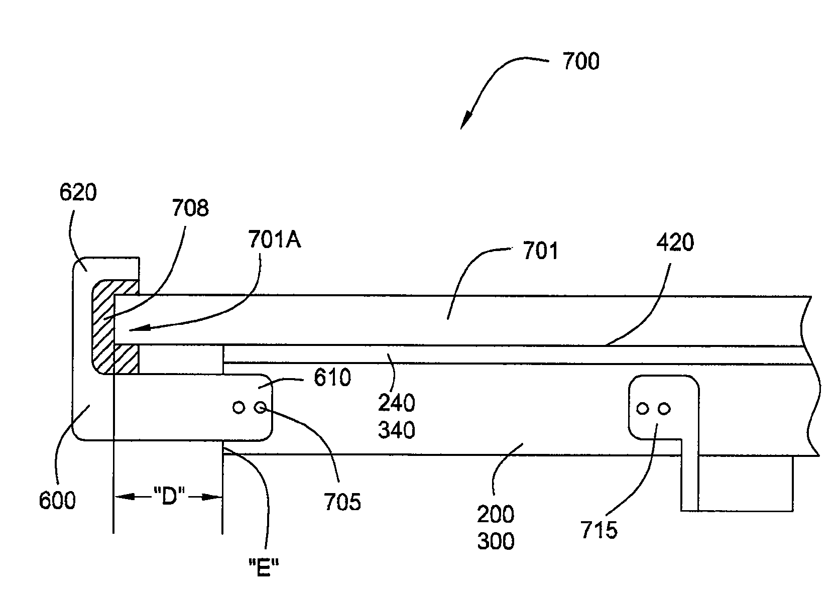
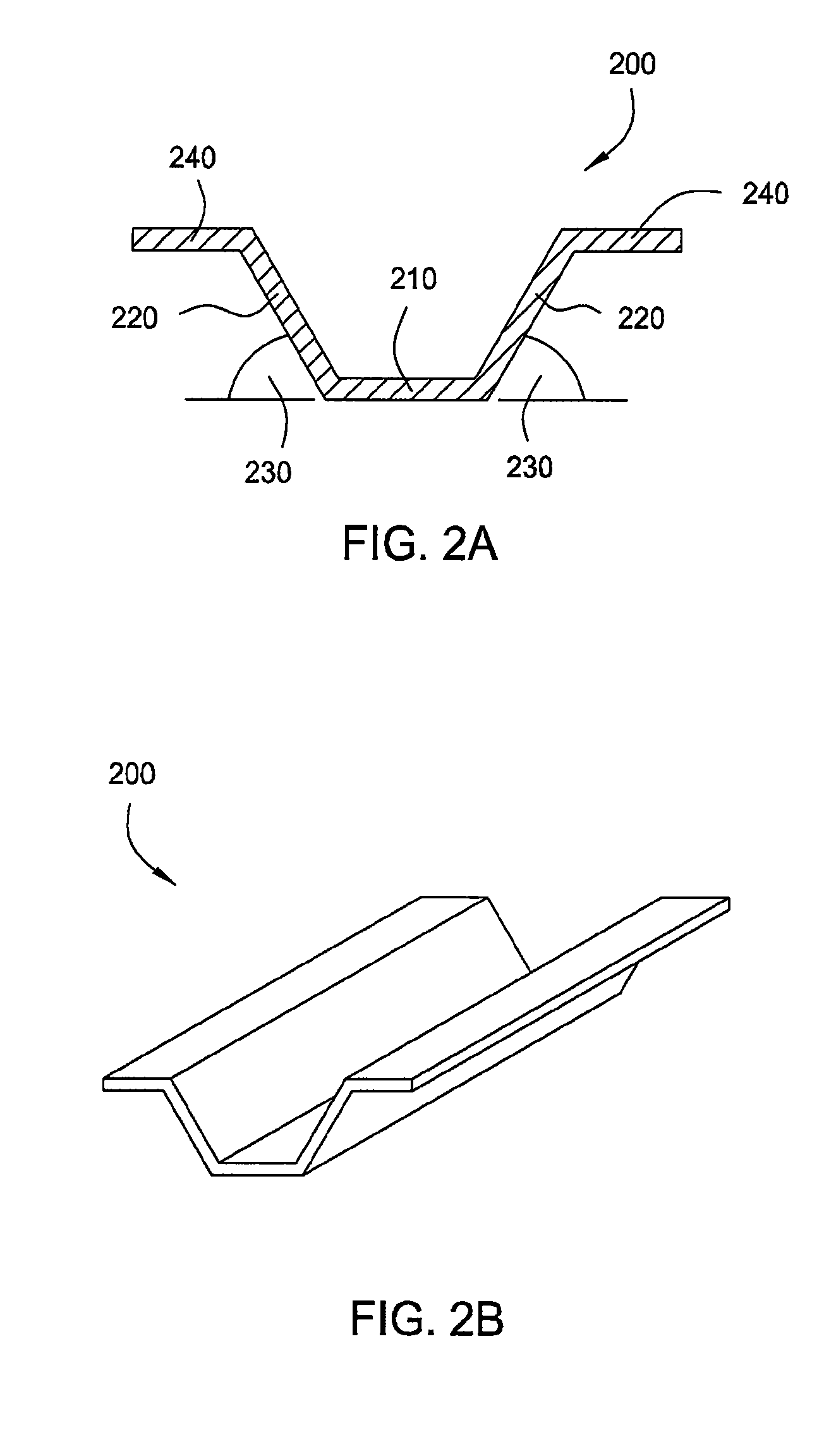
[0034]The present invention generally relates to a simple and cost effective device and method for mounting and supporting solar panels. A solar panel according to the present invention is supported from the backside via a plurality of elongated support members. The elongated support members may have open V-shaped or W-shaped arrangements strong enough to support a solar panel under the required loading but flexible enough to minimize the maximum stress experienced by the solar cell during normal operation and exposure to the environment. The support members may be adhered to the solar panels through strong, flexible glue or double-sided tape that withstands significant environmental loads, such as wind uploading, yet remain flexible enough to minimize stress concentrations in the solar panels. The support members may be attached to a solar panel by a support member attachment module incorporated into an automated solar panel production line. A plurality of solar panels may be field...


PUM

PropertyMeasurementUnit
Adhesion strengthaaaaaaaaaa
Flexibilityaaaaaaaaaa
Adhesivityaaaaaaaaaa

Abstract

The present invention generally relates to a simple and cost effective device and method for mounting and supporting solar panels. A solar panel according to the present invention is supported from the backside via a plurality of elongated support members. The elongated support members may have open V-shaped or W-shaped arrangements and may be adhered to the solar panels through strong, flexible glue or double-sided tape that withstands significant environmental loads, such as wind uploading, yet remain flexible enough to minimize stress concentrations in the solar panels. The support members may be attached to a solar panel by a support member attachment module incorporated into an automated solar panel production line. A plurality of solar panels may be field mounted to a solar panel support structure having one or more piles or the like with at least a lower and upper transverse support rails spanning the plurality of solar panels.

Description

CROSS-REFERENCE TO RELATED APPLICATIONS[0001]This application claims benefit of U.S. provisional patent application Ser. No. 61 / 028,795, filed Feb. 14, 2008 and U.S. provisional patent application Ser. No. 61 / 036,691, filed Mar. 14, 2008, each of which is herein incorporated by reference.[0002]This application is related to U.S. application Ser. No. 12 / 202,199, filed Aug. 29, 2008 and U.S. application Ser. No. 12 / 201,840, filed Aug. 29, 2008.BACKGROUND OF THE INVENTION[0003]1. Field of the Invention[0004]Embodiments of the present invention generally relate to a device and method for mounting and supporting solar panels.[0005]2. Description of the Related Art[0006]Due to environmental concerns and the rise in the cost of traditional energy sources, the demand for use of renewable energy sources is steadily increasing. In particular, significant resources are being invested in developing low cost panels for the production of electricity from solar energy. However, many challenges rem...

Claims


Application Information

Patent Timeline
IPC IPC(8): H01L31/048F24J2/52H01L31/18B23P15/26
CPCF24J2/5203F24J2/5228F24J2/5254F24J2002/4676Y10T29/49355Y02E10/47Y02E10/50H02S20/00F24J2002/5222F24S25/30F24S25/40F24S25/632F24S2025/016F24S2025/601F24S2025/805H02S20/23Y02B10/10Y02P80/20
Inventor UMOTOY, SALVADOR P.SULLIVAN, JEFFREY S.BRENNAN, MIKEGAY, CHARLESCOSTUROS, THEODOSSIOS V.WILLIAMS, GARY D.GOMEZ, OSCAR
Owner APPLIED MATERIALS INC
Learn More