Contact rollers for a winding machine

a technology of contact rollers and winding machines, which is applied in the direction of cranks, mechanical equipment, transportation and packaging, etc., can solve the problems of insufficient eccentricity, inability to meet the needs of movement, and inability to meet the requirements of movemen

Inactive Publication Date: 2002-06-25
ERWIN KAMPF & MASCHFAB
View PDF4 Cites 6 Cited by
  • Summary
  • Abstract
  • Description
  • Claims
  • Application Information

AI Technical Summary

Problems solved by technology

Contact rollers of fixed length can however only work with a relatively limited range of winding rolls.
For very wide machines such a solution is not acceptable since the support axle inside the roller segments is of limited diameter so that the eccentricity necessary for the

Method used


Image

  • Contact rollers for a winding machine
  • Contact rollers for a winding machine
  • Contact rollers for a winding machine

Examples


Embodiment Construction

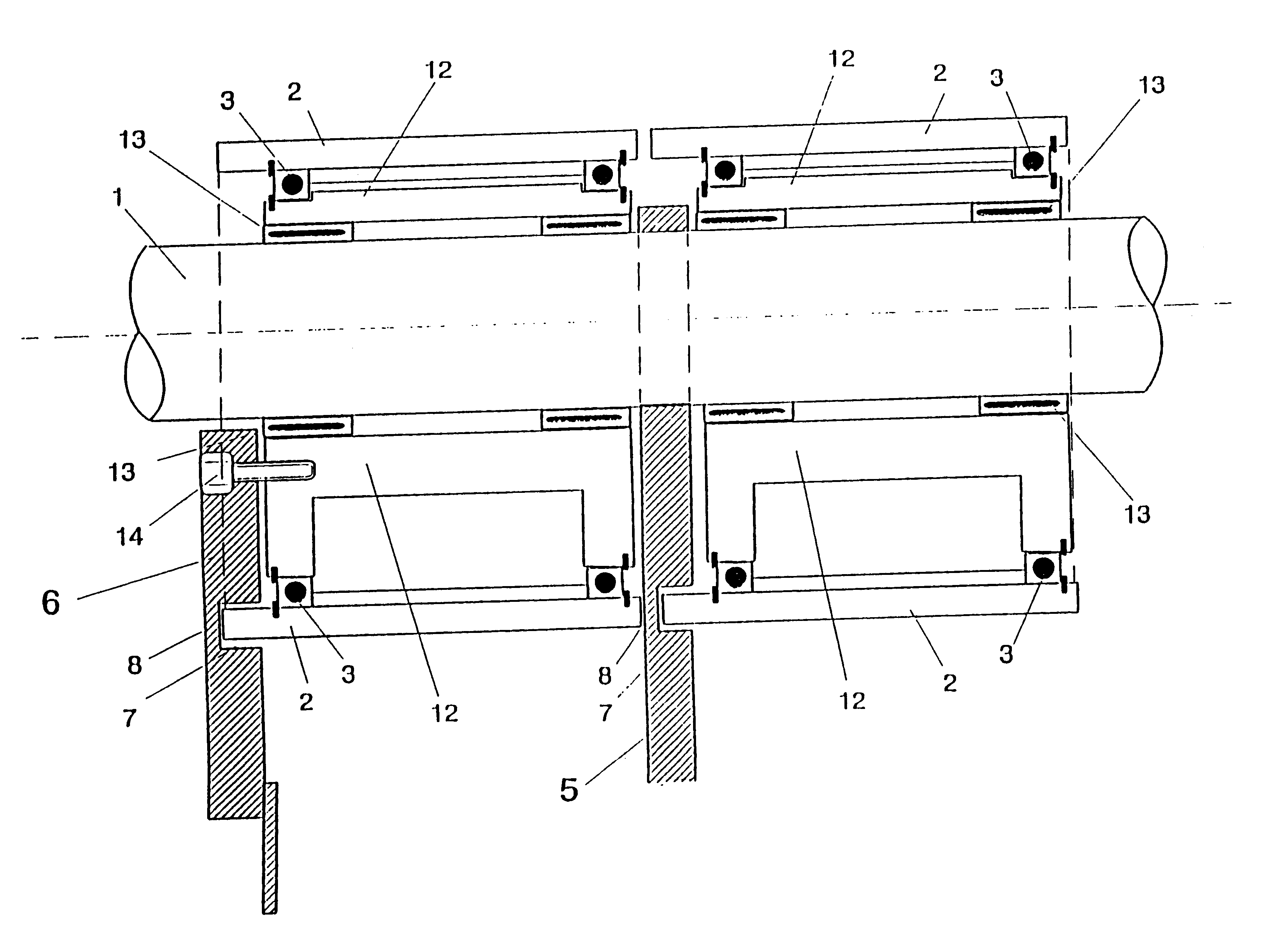
The contact-roller system is part of a winding machine for winding up webs, in particular paper webs or plastic foils. The longitudinally cut web is wound on sleeves to rolls that are held during winding either by a common winding axle or each by two holding heads fitted into the sleeves. In particular at high winding speeds contact rollers are needed around which the web is partially looped and that each are pressed against a winding roll in order to prevent air from being introduced into the winding rolls.

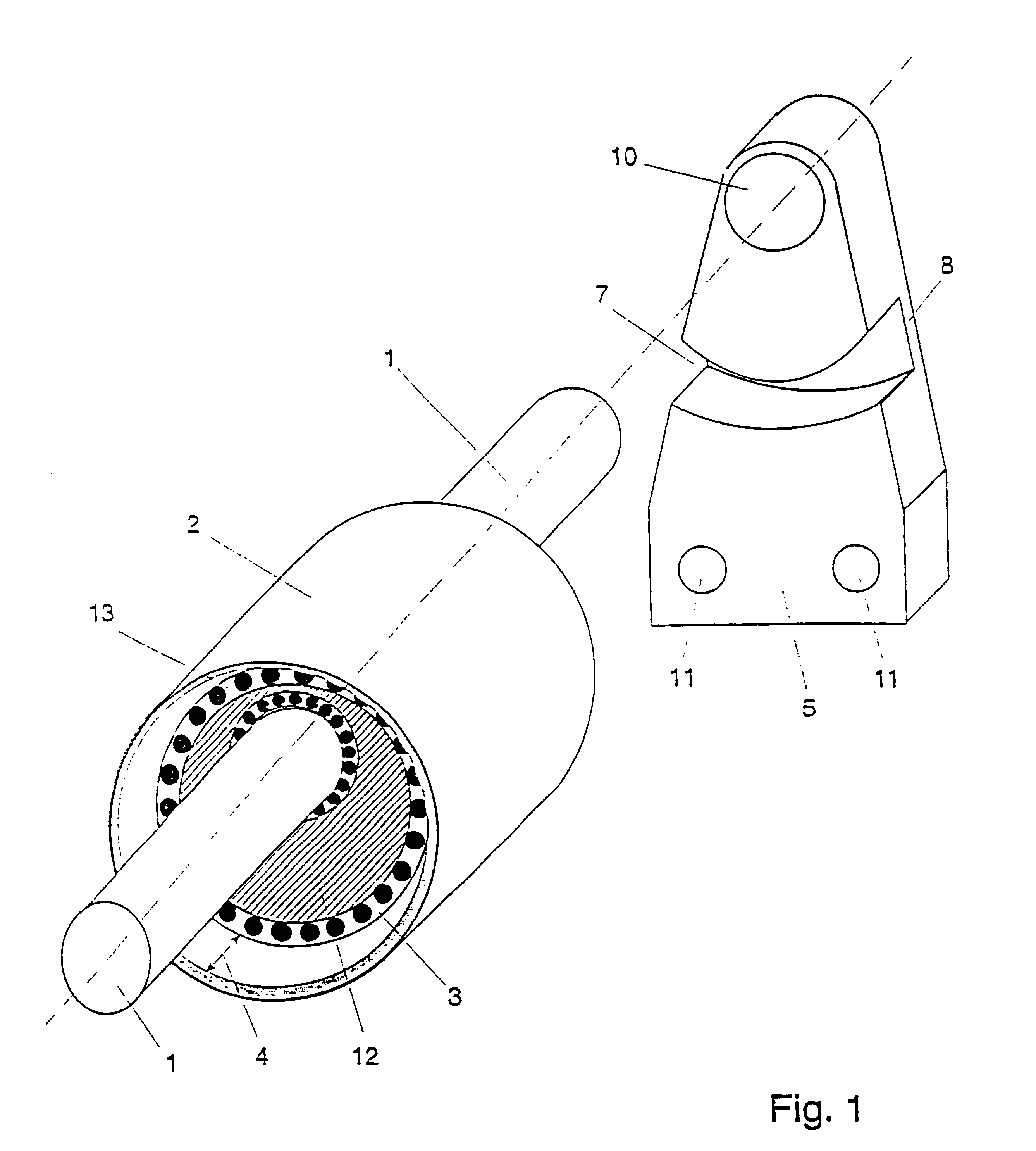
The contact-roller system comprises a row of end-on-end adjacent hollow cylindrical roller segments 2 freely rotatably mounted on a stationary support axle. The axial length of each roller segment 2 is less than the minimum width of a web to be wound up, in this embodiment 200 mm to 300 mm. Adjacent roller segments can be coupled mechanically to each other in order to form a rigid contact roller with an axial length corresponding to the respective winding rolls. The common suppor...


PUM

PropertyMeasurementUnit
Lengthaaaaaaaaaa
Lengthaaaaaaaaaa
Lengthaaaaaaaaaa

Abstract

Contact roller systems comprising several hollow cylindrical roller segments (2) that are mounted next to each other on the front face side in such a way that they can rotate freely on a continuous shaft (1) are already known per se in winding machines. According to the invention, the internal bearing parts of a roller segment (2) terminate on at least one axial end at a distance (4) from the front face of the roller segment (2). A free space is thus formed, whereby parts of a support bearing (5) which supports the shaft (1) and/or parts of an adjusting lever (6) can be arranged therein. The support bearing (5) and/or the adjusting lever (6) have an annular groove (7) in which the end of the roller segment (2) can rotate in a contactless manner. It is possible to keep the gap between two adjacent roller segments (2) as small as possible in order to avoid markings, while still allowing the support bearing (5) and/or adjusting lever (6) to act.

Description

The invention relates to a winding-machine contact-roller system with a plurality of hollow cylindrical roller segments that are arranged end-to-end and freely rotatable on a throughgoing axle and a winding machine having the contact-roller system for winding up a continuously moving web, in particular a paper web or plastic foil.STATE OF THE ARTWinding machines for winding up a running web, for example a paper web or plastic foil, use as is known contact rollers as pressure or squeeze rollers in order to largely prevent trapping of air in the winding roll at high winding speeds. If the winding machine is to wind up webs separated by longitudinal cuts onto respective winding rolls that are carried on coaxial sleeves, it is advantageous to mount the contact rolls for each winding roll for movement in a direction perpendicular to the rotation axis. This allows diameter differences in the various winding rolls to be compensated out. The axial length of each contact rollers should thus ...

Claims


Application Information

Patent Timeline
IPC IPC(8): B65H27/00B65H18/08B65H18/26F16C19/55F16C3/04F16C3/22F16C19/00B65H19/22
CPCB65H18/26B65H27/00F16C23/10F16C3/22F16C19/55B65H2301/4148B65H2402/341B65H2404/1321B65H2404/1342B65H2404/1344B65H2404/17B65H2404/13211B65H2402/30
Inventor HUTZENLAUB, ARMINKUNKEL, DIETMAR
Owner ERWIN KAMPF & MASCHFAB
Why Eureka
Try Eureka