Yarn winding machine

A yarn winding machine and yarn technology, applied in textiles and papermaking, conveying filamentous materials, thin material processing, etc., can solve the problem of increased slack in the bobbin, and achieve the effect of a simple mechanism

Active Publication Date: 2004-10-06
MURATA MASCH LTD
View PDF3 Cites 37 Cited by
  • Summary
  • Abstract
  • Description
  • Claims
  • Application Information

AI Technical Summary

Problems solved by technology

Therefore, the amount of slack residing on the slack removing roller cannot be increas...

Method used


Image

  • Yarn winding machine
  • Yarn winding machine
  • Yarn winding machine

Examples


no. 1 example

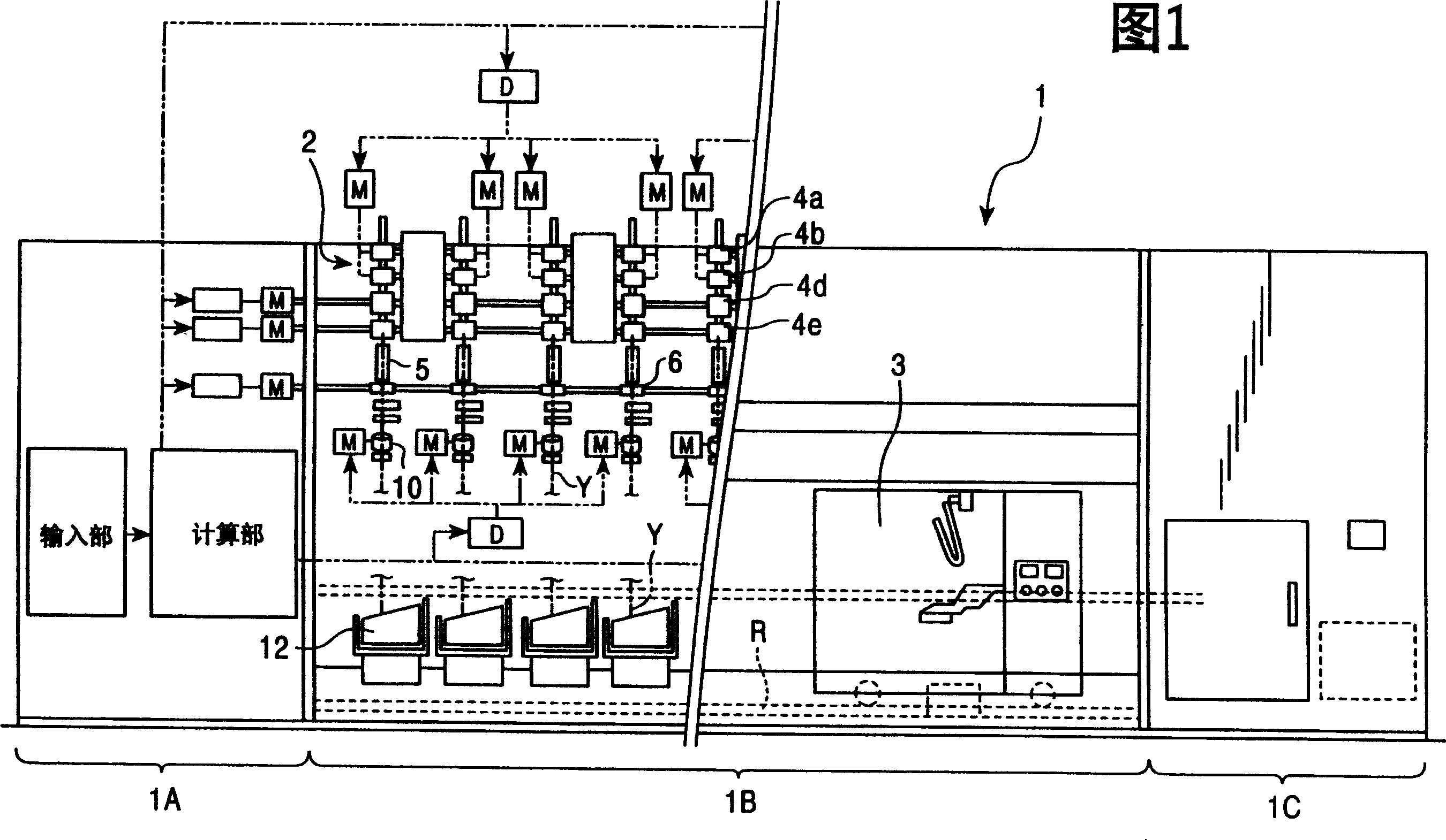
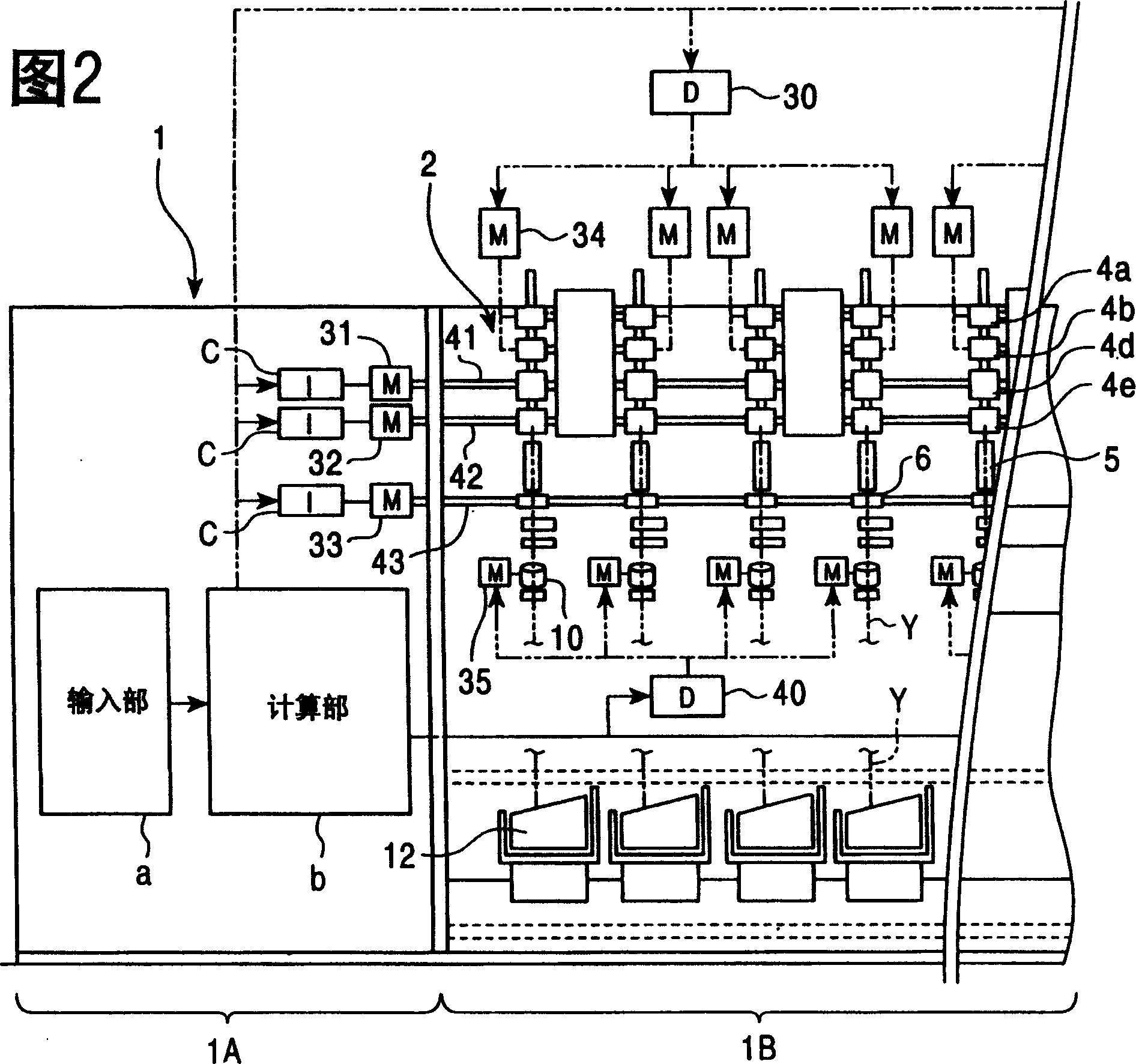
[0032] Fig. 1 is a front view of an example of a spinning machine 1 to which the present invention is applied. FIG. 2 is a schematic enlarged view of a part of the internal structure of the spinning machine 1 .

[0033] The spinning machine is constituted by, for example, an air spinning machine. The main components of the spinning machine 1 include: a control section 1A; a spinning section 1B, in which a large number of spinning units 2 are arranged side by side; a blower section 1C; and a work trolley 3, which includes a yarn Splicing device, and can run freely between the spinning units 2 along the track R. In the present embodiment, the spinning machine 1 is used to form cone yarns, however, it may also be used to form parallel cheese packages.

[0034] The control section 1A of the spinning machine 1 implements the following control: controlling the operation of the drive motors 31, 32, 33 of the drive shafts 41, 42, 43 for supplying all spinning units 2 constituting th...

no. 2 example

[0080] For the spinning machine 1, it can adopt such an embodiment that the winding speed of the bobbin 16 is reduced according to a preset deceleration program to increase the amount of slack, regardless of the slack remaining in the yarn. The slack of the device 10 eliminates slack on the roller 21 . For example, it is conceivable that the amount of slack residing on the slack removing roller 21 can be recovered for a specified period of time by repeatedly performing the steps of rotating the rocker arm 14 to keep the package 16 separated from the drum 13 for a predetermined period of time. , and then the rocker arm is rotated in the return direction so that the bobbin 16 is in contact with the drum 13 again. This embodiment ensures that the slack is recovered within a certain time. As a result, even if the amount of slack residing on the slack eliminating roller 21 decreases during the operation of the spinning machine, the tension adjustment in the yarn winding procedure ...

no. 3 example

[0083] A yarn take-up machine used in a spinning machine, a twisting machine, and a false twisting machine can wind a yarn fed by a yarn feeding device while using a traversing device to traverse the yarn. Such yarn winding machines are usually configured to form several bobbins simultaneously. In this case, as described in Japanese Patent Laid-Open Document No. 2871595, the traversing device may be constructed such that the traversing guides for the individual packages are fixed on a common drive shaft (traversing rod) , the common drive shaft is used to collectively drive all traverse guides.

[0084] It is known that both laps and saddle humping problems occur when yarn winding machines wind yarn into packages by means of traversing devices comprising reciprocating traversing guides. Lapping is a phenomenon that occurs when yarn is wound multiple times at the same location. Saddle humping is a phenomenon that occurs when the yarn is wound more at the opposite ends of the ...


PUM


Abstract

The present invention prevents the amount of slack from decreasing below a predetermined value when a yarn slack eliminating device is used to control a winding tension during a yarn winding process executed by a spinning machine. A winding device 12 winds a yarn spun by a spinning device 5, into a package 16, while a yarn slack eliminating device 10 is eliminating the slack of the yarn. During this process, when it is detected that the amount of slack in the yarn slack eliminating device 10 decreases below a predetermined value, the package 16 is separated from a rotating drum 13 to reduce a winding speed to increase the amount of slack. At this time, the time for which the package 16 remains separated is controlled in accordance with the winding diameter of the package 16 to adjust the aspect of reduction of the winding speed. When the amount of slack is increased, the time for which the reduction of the winding speed is continued and the amount of speed reduction are adjusted taking the winding diameter of the package into account. Therefore, the optimum speed reduction aspect can be set in accordance with a variation in the inertia moment of the package.

Description

technical field [0001] The present invention relates to a yarn winding machine which utilizes a yarn slack eliminating device to control the winding tension; in particular, the object of the present invention is to prevent the yarn from remaining on the slack eliminating roller of the yarn slack eliminating device The amount of slack is reduced below a predetermined value. Background technique [0002] As an example, a cone package is formed using a spinning machine in which a spinning device produces a spun yarn using a sliver (fiber bundle) as a raw material, and a take-up device winds the spun yarn into a coil. Wind into a bobbin. In this case, in particular, if the winding tension is not controlled prior to winding, the tension in the yarn will unfavorably vary periodically as the yarn traverses. This is because the winding speed of the yarn (peripheral speed of the package) is different between the small diameter side and the large diameter side of the cone yarn, so t...

Claims


Application Information

Patent Timeline
IPC IPC(8): B65H51/22B65H59/18B65H59/38D01H9/10
CPCB65H2701/31B65H59/385B65H59/18B65H51/22B65H57/003D01H9/10
Inventor 平尾修重山昌澄八木宏幸
Owner MURATA MASCH LTD
Why Eureka
Try Eureka