Air guide duct for vehicle

a technology for air guide ducts and vehicles, which is applied in the direction of ducting arrangements, roofs, vehicle cleaning, etc., can solve the problems of unpleasant noises, short circuits, and malfunctions of on-vehicle equipment, and achieve the effects of avoiding condensation, avoiding short circuits, and avoiding short circuits

Inactive Publication Date: 2002-06-25
INOAC CORP
View PDF6 Cites 72 Cited by
  • Summary
  • Abstract
  • Description
  • Claims
  • Application Information

AI Technical Summary

Problems solved by technology

Although such blow molded air guide duct has advantages that it has appropriate rigidity, it is light weighted, and it can be molded at low cost, it has a drawback that in case where a large difference in temperature exists between an interior air flowing space and the exterior, condensation is likely to occur because of small thickness of the air guide duct.
Therefore, there have been such inconveniences that when water drops are formed from this condensation and fall on steel components such as the vehicle body, brackets, and so on, this will be a cause of rust, or when the water drops fall on the aforesaid wire harnesses or the electrical equipments of the electrical component system, this will cause a short circuit or incur malfunction or breakdown of the on-vehicle equipments.
Further, unpleasant noises may sometimes occur in the event that a duct body formed of polyethylene comes in contact with other members.
However, it has been a problem that cost for material of the urethane sheet and assembly process are required, and production cost will be increased.
Still further, it has been pointed out that since the air conditioner unit and the air outlets spatially communicate with each other by way of the air guide ducts, operating noises of a blower which is driven by the air conditioner unit spread in the air flowing space in the air guide duct and are leaked into the cockpit.
However, in many cases, the wire harnesses are kept exposed while extending inside the aforesaid vehicle interior members.
Therefore, there has been a fear that the wire harnesses may oscillate with vibrations of the vehicle body while driving, may come into contact with other members, or may be partially pulled.
There has been a further anxiety that in some cases, a conductive wire may be exposed due to wear of covering material, resulting in a short circuit or a break of the wire.
Furthermore, since the wiring arrangement and the binding work of the wire harnesses are rather annoying and time consuming, it has been sought for to realize rationalization and simplification of the work.
Accordingly, the vibrations of the air conditioner unit are transmitted to the aforesaid steering shaft which is connected to the reinforce bar, and it has been pointed out that the vibrations will give unpleasant feeling to the driver who is handling the steering wheel.

Method used


Image

  • Air guide duct for vehicle
  • Air guide duct for vehicle
  • Air guide duct for vehicle

Examples


first embodiment

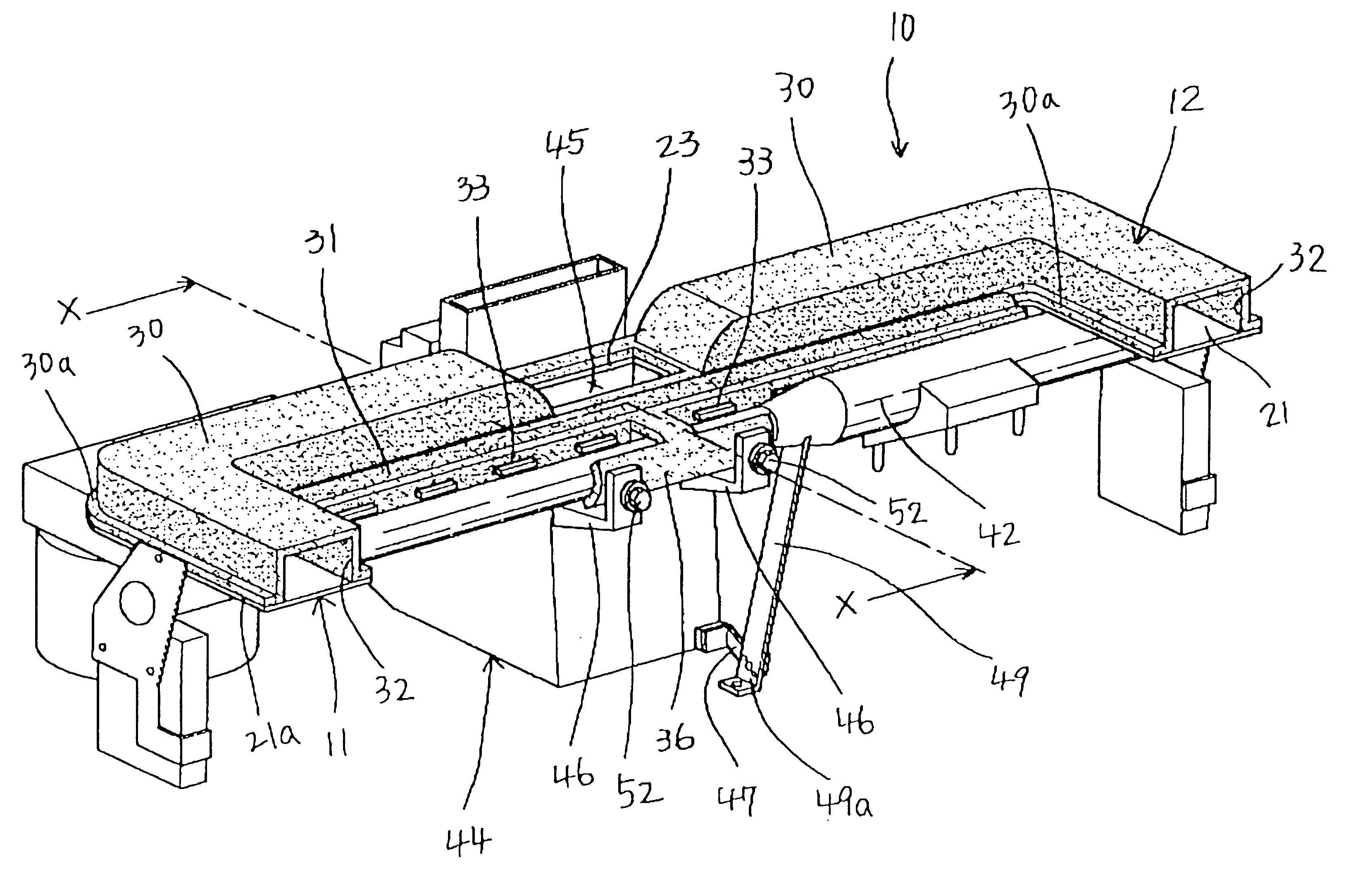
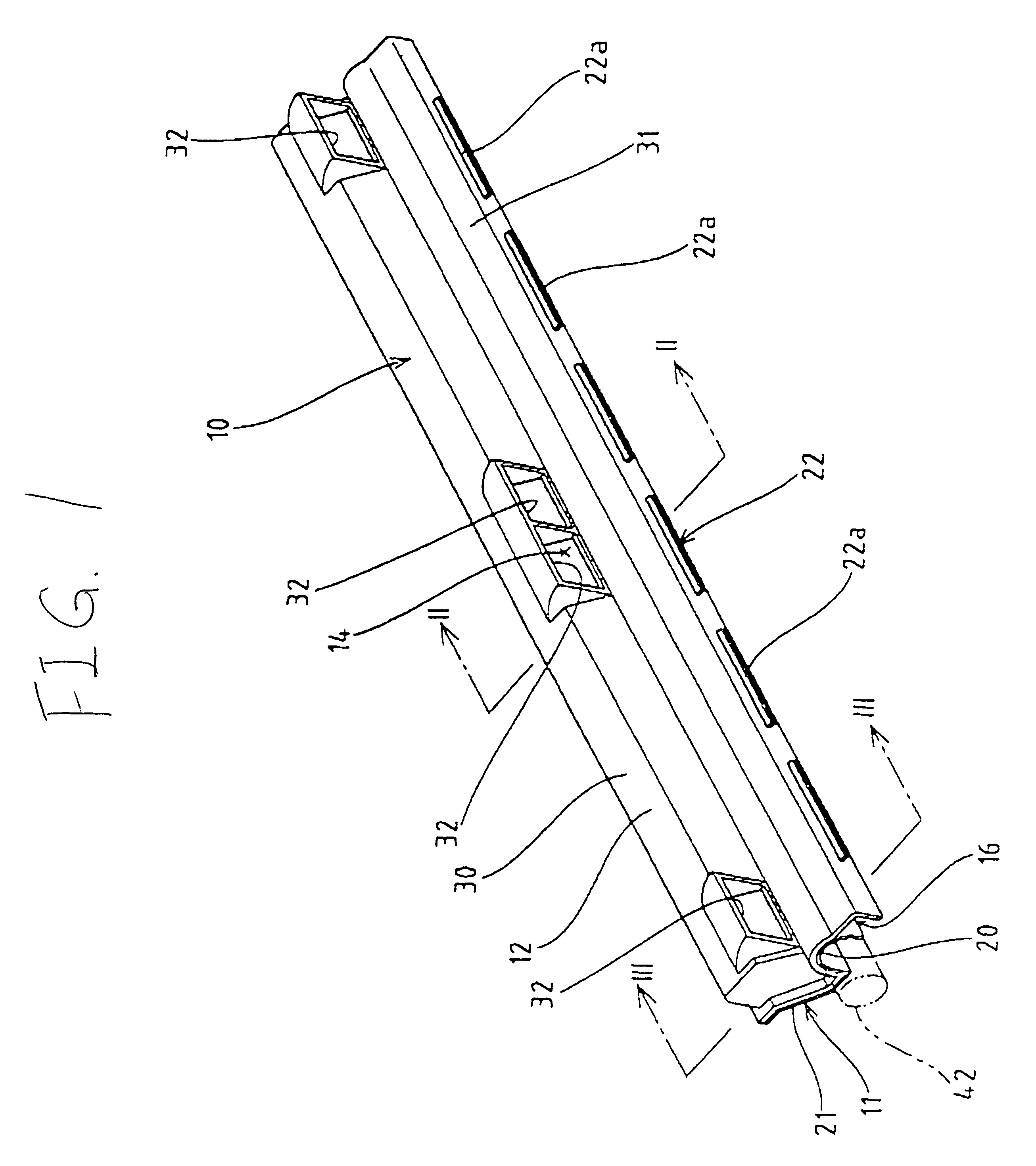
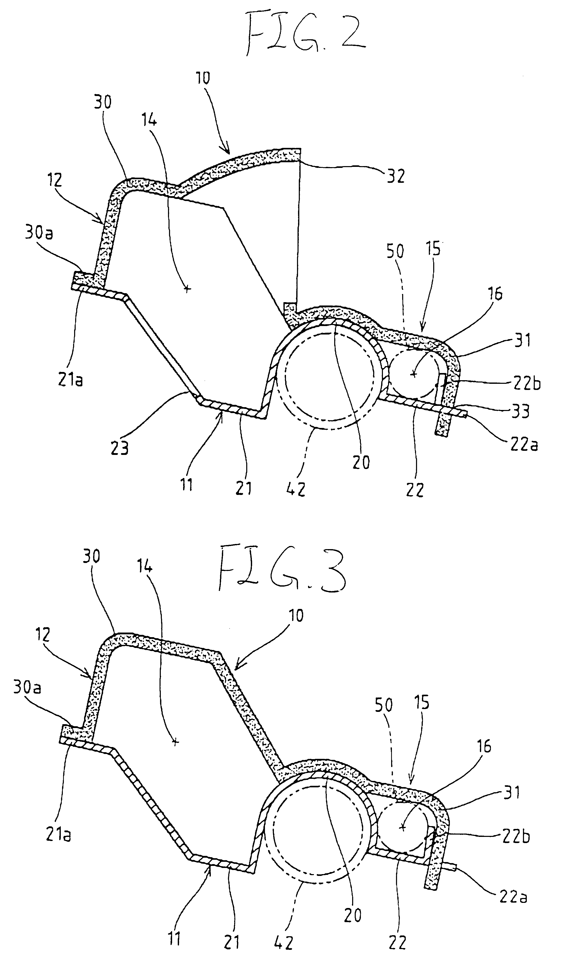
FIG. 1 is a perspective view of an air guide duct 10 according to a first embodiment of the present invention, FIG. 2 is a sectional view taken along a line II--II in FIG. 1, FIG. 3 is a sectional view taken along a line III--III in FIG. 1, and FIG. 4 is a sectional side view showing a state wherein the air guide duct 10 as shown in FIG. 1 is installed inside an instrument panel 40. The air guide duct 10 in this embodiment consists of a first base body 11 formed of a resin sheet material having a determined thickness and a second base body 12 formed of foamed resin sheet material having a determined thickness. These first base body 11 and the second base body 12 are connected to each other in a longitudinal direction to form an elongated rectilinear hollow body and to integrally form a mounting part 15 for containing and protecting wire harnesses (wire elements) 50 of an electrical component system. The air guide duct 10 is designed on the premise that it is directly fixed to a rein...

second embodiment

The Second Embodiment

FIGS. 13 and 14 are a perspective view and a sectional side view of an air guide duct for a vehicle according to a second embodiment of the invention. In the air guide duct 10 in this embodiment, the foamed resin sheet material forming the aforesaid second base body 12 is partially made larger in size, and a middle portion of the cover piece 31 in a longitudinal direction is elongated. Although the first base body 11 and the second base body 12 are different in shape from those of the above described first embodiment, the first base member 11 is molded from resin sheet material having rigidity to form one duct half, and the second base body 12 is molded from foamed resin sheet material to form the other duct half. The air flowing space 14 is defined inside by joining the first base body 11 and the second base body 12. This embodiment is substantially the same as the air guide duct 10 in the aforesaid first embodiment in that the aforesaid first base body 11 is p...


PUM


Abstract

There is provided an air guide duct for a vehicle, the air guide duct connected for communication with an air conditioner unit provided in a passengers' room in a vehicle, the air guide duct adapted to pass and guide temperature regulated air supplied from the air conditioner unit, the air guide duct comprising a first base body constituting one duct half, the first base body including a mounting part for allowing a wire element of an electrical component system to be contained along the air guide duct, and a second base body constituting the other duct half, the second base body covered over the first base body to define an air flowing space therebetween, the second base body including a cover piece which laterally extends from the duct, wherein the mounting part containing the wire element is so constructed as to be covered with the cover piece.

Description

1. Field of the InventionThe present invention relates to an air guide duct for a vehicle, and more particularly, to an improvement of the air guide duct which is disposed inside vehicle interior members such as an instrument panel, a floor console, a ceiling panel etc. so as to communicate air outlets provided in the interior members with an air conditioner unit thereby guiding temperature regulated air from the air conditioner unit to the air outlets.2. Background of the InventionInside a cockpit in a vehicle such as an automobile, there are mounted various vehicle interior members such as a instrument panel on which various types of on-vehicle equipments such as a meter board, an air conditioner operating panel, an audio unit, and so on are installed, a floor console disposed on a floor between a driver's seat and an passenger's seat, and a ceiled panel attached to a ceiling of the cockpit. In a forward area of the cockpit, there is installed an air conditioner unit adapted to be...

Claims


Application Information

Patent Timeline
Patent Type & Authority Patents(United States)
IPC IPC(8): B60H1/00B62D25/14B62D25/08F24F13/02
CPCB60H1/0055B62D25/145B62D25/142B60H1/00564B60H1/242
Inventor SUZUKI, HIROSHISHIKATA, KAZUSHINUMAZAWA, SHIGEOKAMIYA, TOMOHIRO
Owner INOAC CORP
Why Eureka
Try Eureka