Ink jet recording method and ink jet recorder for ejecting controlled ink droplets

a technology of ink jet and recording method, which is applied in the direction of printing, inking apparatus, other printing apparatus, etc., can solve the problems of ink droplets ejecting in wrong directions, needless ink droplets ejecting, etc., and achieve good recording quality and stably ejecting ink

Inactive Publication Date: 2002-07-16
BROTHER KOGYO KK
View PDF3 Cites 13 Cited by
  • Summary
  • Abstract
  • Description
  • Claims
  • Application Information

AI Technical Summary

Benefits of technology

It is an object of the present invention to provide an ink jet recording method for good recording quality, which makes it possible to stably eject ink by changing the number of ejected ink droplets for a dot if the print instruction for the dot immediately follows and / or immediately precedes non-print instruction. It is another object to provide an ink jet recorder and a storage medium for use with such a recording method.
The recorder may further include a temperature sensor for measuring the temperature of the ink or the ambient temperature around the ink. If the one print instruction immediately follows or immediately precedes no other when the measured temperature is lower than a predetermined temperature, the actuator may eject ink droplets which are N (N.ltoreq.2) in number. If the one print instruction immediately follows or immediately precedes no other when the measured temperature is equal to or higher than the predetermined temperature, the actuator may eject ink droplets which are M (M<N) in number. This makes it possible to keep the ejection stable even if the viscosity of the ink changes with temperature.

Problems solved by technology

For example, the vibration may cause the ink droplet to be ejected in a wrong direction, or a needless ink droplet to be ejected.
This is liable to make ink droplets ejected in wrong directions and / or needless ink droplets ejected.

Method used


Image

  • Ink jet recording method and ink jet recorder for ejecting controlled ink droplets
  • Ink jet recording method and ink jet recorder for ejecting controlled ink droplets
  • Ink jet recording method and ink jet recorder for ejecting controlled ink droplets

Examples


Embodiment Construction

An ink droplet ejector embodying the present invention is similar in mechanical structure to that shown in FIG. 6, and will therefore not be described.

An embodiment of the ink droplet ejector 600 was tested. Each ink channel 613 of the ejector had a length L of 6.0 mm. Each nozzle 618 of the ejector had a length of 75 .mu.m, a diameter of 26 .mu.m on its outer side for ejection of ink, and a diameter of 40 .mu.m on its inner side adjacent to the associated channel 613. The ink used for the test had a viscosity of about 2 mPa.multidot.s and a surface tension of 30 mN / m at a temperature of 25.degree. C. The ratio L / a (=T) of the length L to the sound velocity a in the ink in each ink channel 613 was 9.0 .mu.sec.

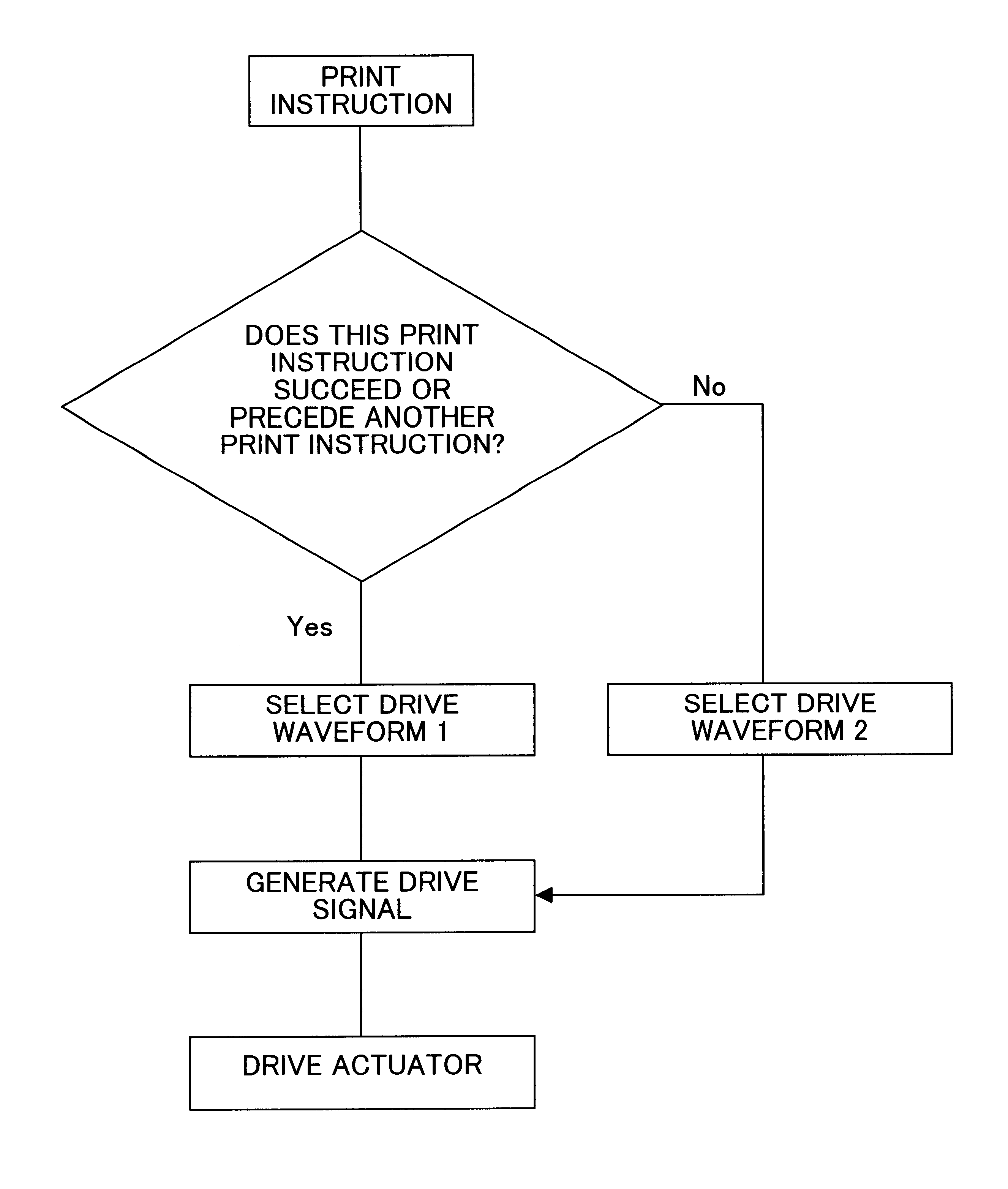
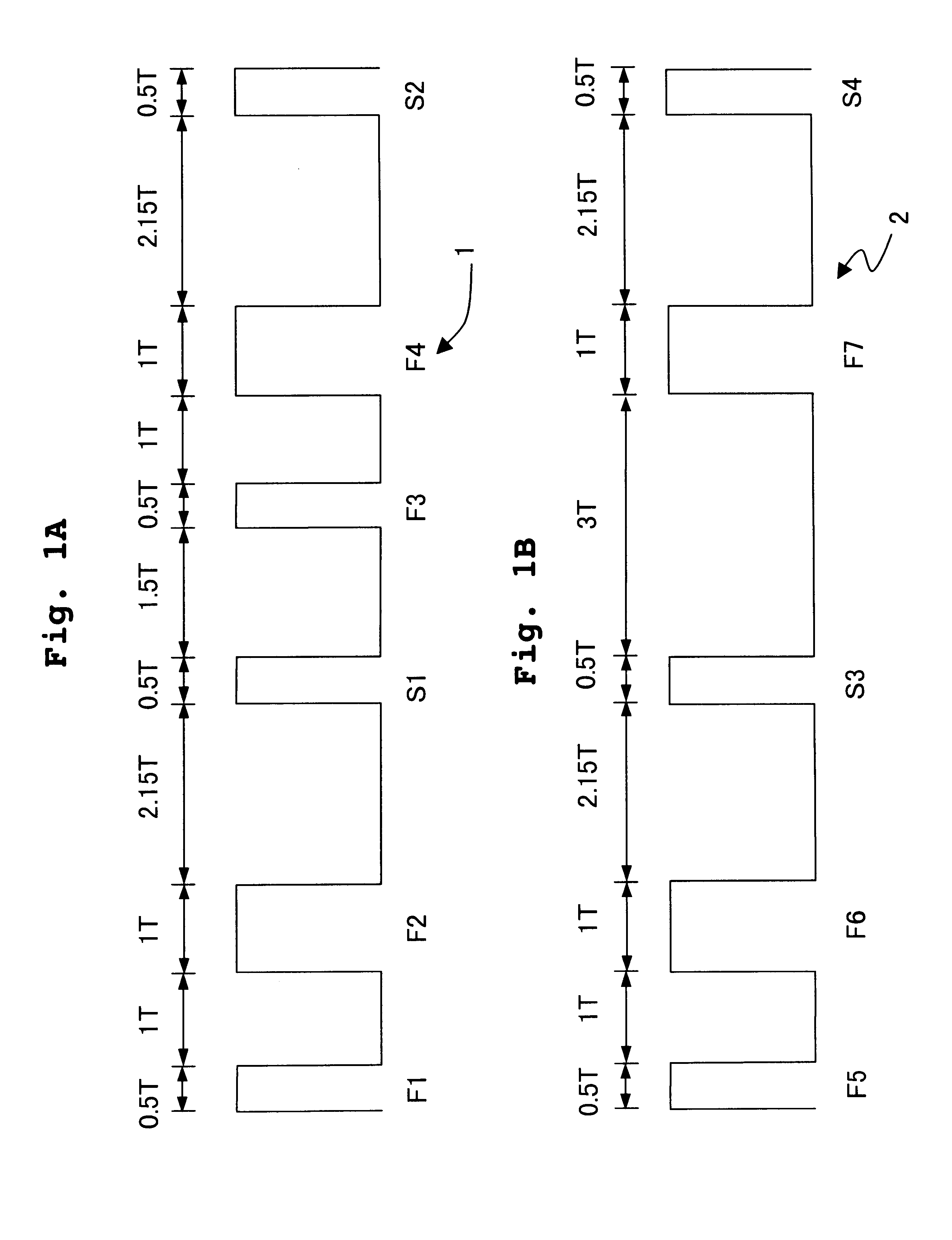
FIG. 1A shows a drive waveform 1 for normally ejecting four ink droplets at different times from one of the ink channels 613 in accordance with a print instruction for one dot. The drive waveform 1 includes ejection pulses F1, F2, F3 and F4 and ejection stabilization pulses S1 ...


PUM


Abstract

Serial dots are printed with a drive waveform 1 for section of four ink droplets per dot from a nozzle. If one print instruction for a dot immediately follows and immediately precedes no others, a drive waveform 2 for ejection of less than four ink droplets per dot from a nozzle is selected for stable printing even under a condition where, if the drive waveform 1 were used, the ink droplets might be ejected in wrong directions, and / or useless ink droplets might be ejected.

Description

BACKGROUND OF THE INVENTION1. Field of the InventionThe present invention relates to an ink jet recording method and an ink jet recorder, and specifically an ink jet recording method and an ink jet recorder which can control a number of ink droplets for forming a dot, and a storage medium for storing a program for driving the recorder.2. Description of the Related ArtA known conventional ink ejector of the ink jet type has ink channels and nozzles each communicating with one of the channels. The volume of each ink channel can be changed by the deformation of a piezoelectric ceramic or the like. When the channel volume decreases, ink in the ink channel is ejected as droplets through the associated nozzle. When the channel volume increases, the ink channel is supplied with ink from an ink supply.Such a conventional ink ejector 600 is shown in section in FIG. 6 of the accompanying drawings. The ink ejector 600 includes an actuator substrate 601 and a cover plate 602. The actuator subst...

Claims


Application Information

Patent Timeline
Patent Type & Authority Patents(United States)
IPC IPC(8): B41J2/045B41J2/01B41J2/055
CPCB41J2/04563B41J2/04581B41J2/04588B41J2202/10
Inventor TAKAHASHI, YOSHIKAZU
Owner BROTHER KOGYO KK
Why Eureka
Try Eureka