

Magnet roll having an anisotropic bonded magnet portion containing rare earth-iron-nitrogen magnet powder
a rare earth-iron-nitrogen magnet powder and anisotropic bonding technology, which is applied in the direction of magnets, magnet bodies, instruments, etc., can solve the problems of limited magnetic flux density, inability to meet the demand of higher magnetic field, and limited magnetic force distribution, so as to achieve high and uniform surface magnetic flux density
- Summary
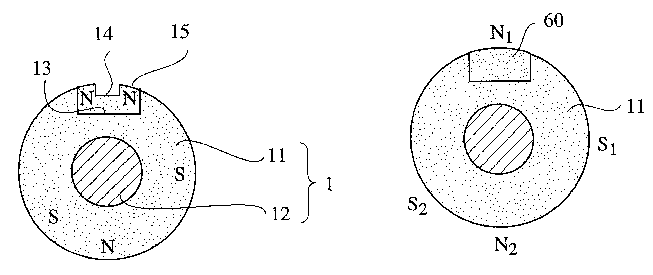
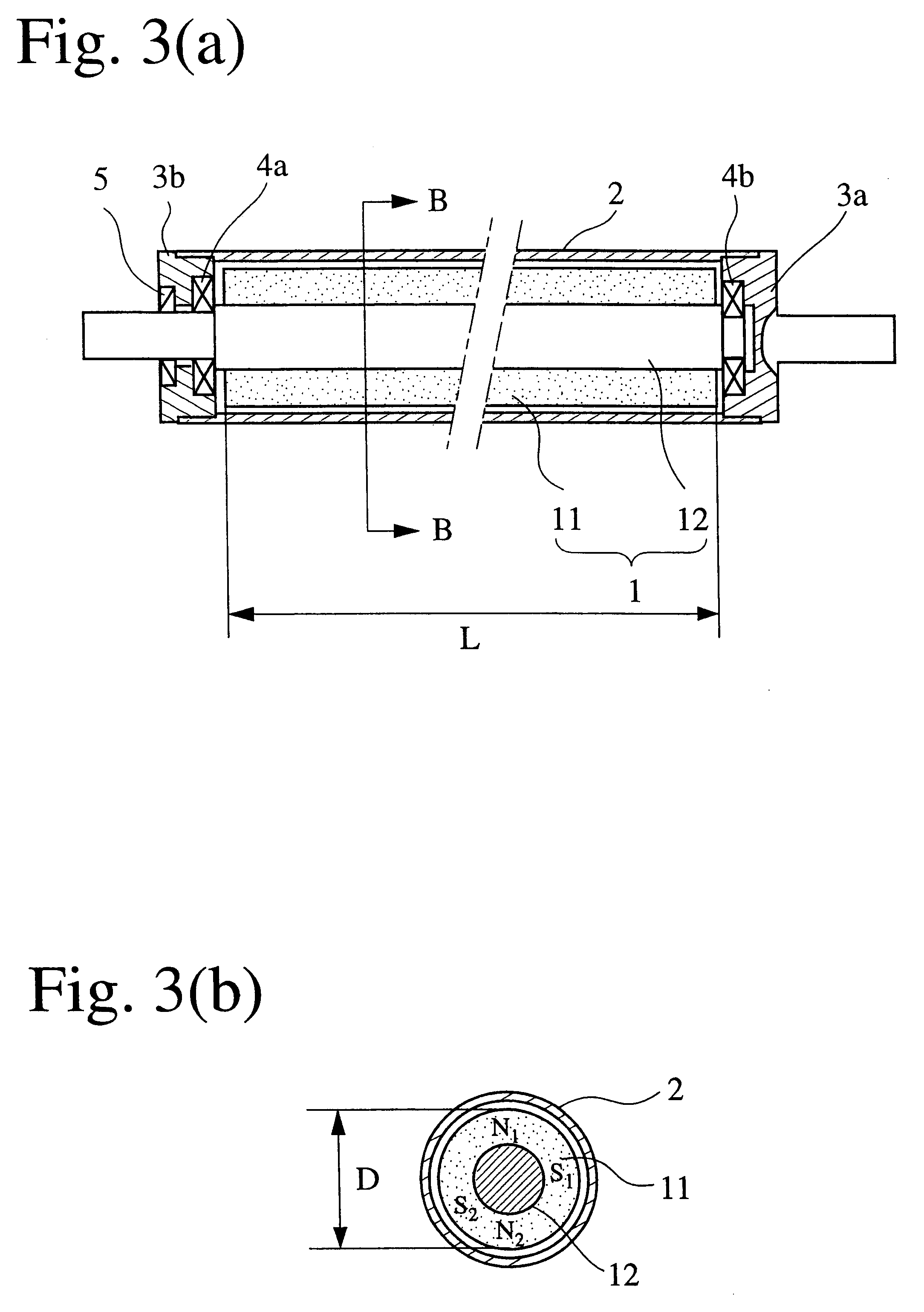
- Abstract
- Description
- Claims
- Application Information
AI Technical Summary
Benefits of technology
Problems solved by technology
Method used
Image

Examples
examples 1-7
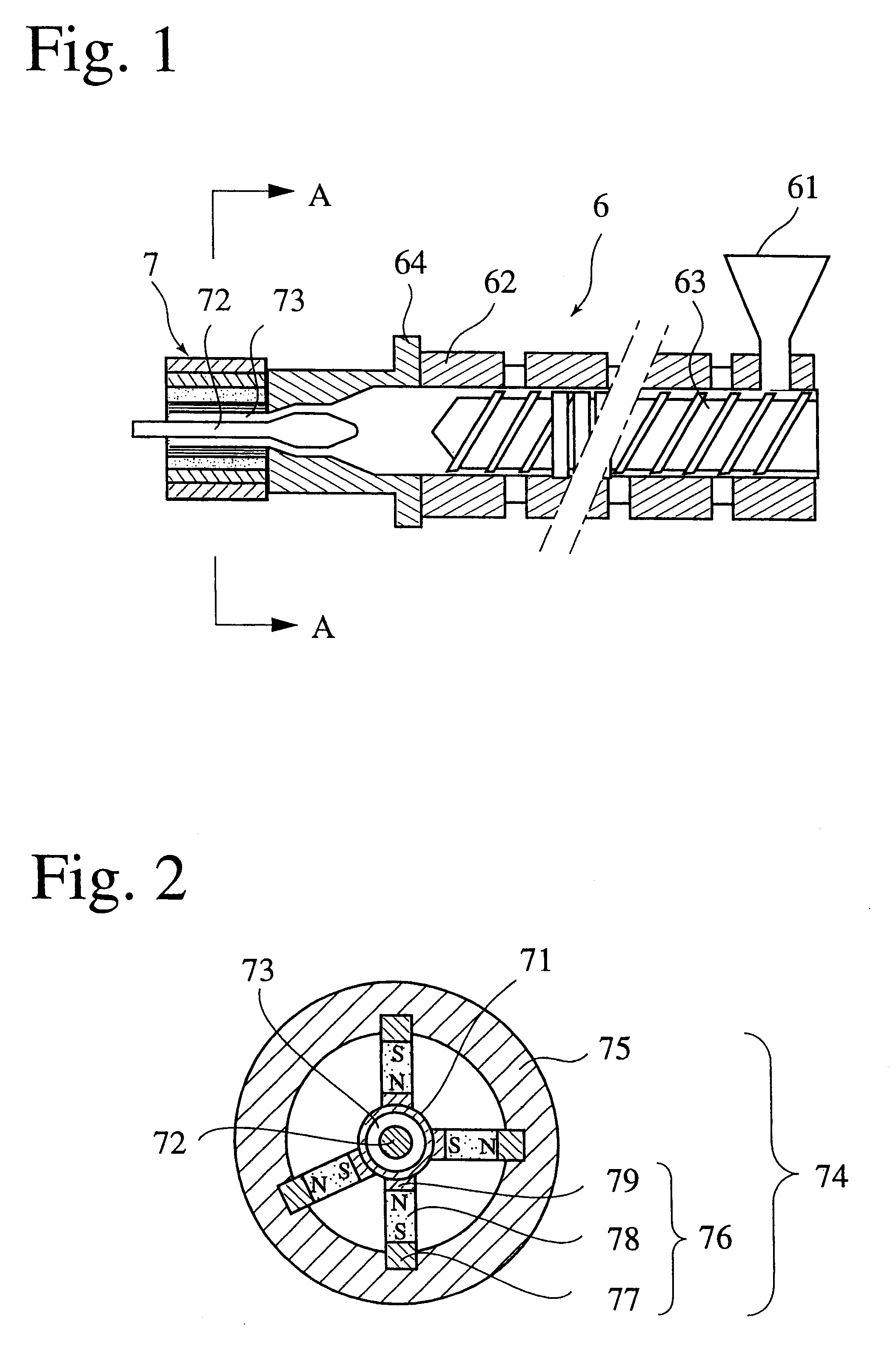
Sm, Fe and C each having a purity of 99.9% were mixed to provide compositions of matrix alloys shown in Table 1, and melted in a high-frequency furnace in an argon gas atmosphere to prepare matrix alloy ingots. In addition to this, quenched thin ribbons obtained by using a twin-roll strip casting machine equipped with two cooling copper rolls may be used for preparing the matrix alloys. Further, a SM--Fe--C alloy obtained by reduction diffusion of a rear earth oxide, an Fe alloy and Ca may also be used.
The resultant matrix alloy was pulverized to an average particle size of about 100 .mu.m or less, subjected to a heat treatment at 400-500.degree. C. for 1-10 hours in a nitrogen gas atmosphere for nitriding. Further, fine pulverization was carried out by a jet mill (a ball mill may be used) to an average particle size (dp) of 1-10 .mu.m, to provide Sm--Fe--C--N alloy powder having a coercive force of 5 kOe or more. For the measurement of an average particle size dp of the alloy powde...
examples 8-10
Comparative Examples 6, 7
Magnet powder having an average particle size of 2-9 .mu.m (EXAMPLES 8-10), magnet powder having a small average particle size (COMPARATIVE EXAMPLE 6) and magnet powder having a large average particle size (COMPARATIVE EXAMPLE 7) were studied. Nitride magnet powder was produced under the same conditions as in EXAMPLES 1-7, and each magnet powder was formed into a magnet roll to conduct the same evaluation as in the EXAMPLES. The results are shown in Table 2.
Table 2 indicates that a high surface magnetic flux density and uniformity are obtained in the case of rare earth nitride magnet powder having an average particle size of 2-9 .mu.m. When the average particle size is small (COMPARATIVE EXAMPLE 6) or large (COMPARATIVE EXAMPLE 7), the surface magnetic flux density is low with poor uniformity.
examples 11-15
Magnet rolls were produced and their characteristics were examined under the same conditions as in EXAMPLES 1-7, except for mixing Sm, Fe and M each having a purity of 99.9% to provide compositions of matrix alloys shown in Table 4, and melting the resultant mixtures in a high-frequency furnace in an argon gas atmosphere to prepare matrix alloy ingots. The heat resistance is expressed by the ratio of a decrease in surface magnetic flux density after each magnet roll was placed in an environment at 80.degree. C. for 50 hours.
PUM
 Abstract
Description
Claims
Application Information