
Safety brake for in-line skates

a safety brake and in-line skate technology, applied in the direction of skateboards, roller skates, sport apparatus, etc., can solve the problems of affecting the safety of in-line skates, damage to the wheels, and the inability to initiate push start with one's skates aligned,

Inactive Publication Date: 2002-07-30
HEMISPHERE GROUP
View PDF19 Cites 3 Cited by
  • Summary
  • Abstract
  • Description
  • Claims
  • Application Information

AI Technical Summary

Problems solved by technology

This is awkward for trying to stop or to hold one's ground against being pushed, or for obtaining a quick start.
It is also awkward and potentially will trip the skater if used to stop while going backwards.
While one can perform a T-stop, such a stop will damage the wheels and would be difficult to engage while moving backwards.
However, a push start cannot be initiated with one's skates aligned.
While this brake can provide a push start, the teeth can damage the wheel.
In addition, although the teeth may not engage when the wheel is rotating forward, they can cause some drag on the wheel and may cause skidding and wheel damage.
Furthermore, it is not possible to provide a controlled and variable braking force.
Even if one could skate backwards somehow, when the brake is applied, it is abrupt and could cause skidding, damage to the wheel, and / or trip the skater.
More importantly, when skating forward, if one tilted one's foot, the brake could catch and trip the skater.
If the skater happens to lean forward while skating forward, frictional reaction force will tend to push the wheel toward the back of the skate, thus deactivating or reducing the brake force.

Method used


Image

  • Safety brake for in-line skates
  • Safety brake for in-line skates
  • Safety brake for in-line skates

Examples


Embodiment Construction

)

The detailed description set forth below in connection with the appended drawings is intended as a description of a presently preferred embodiment of the invention and is not intended to represent the only forms in which the present invention may be constructed and / or utilized. The description sets forth the functions and the sequence of steps for constructing and operating the invention in connection with the illustrated embodiments. However, it is to be understood that the same or equivalent functions and sequence may be accomplished by different embodiments that are also intended to be encompassed within the spirit and scope of the invention.

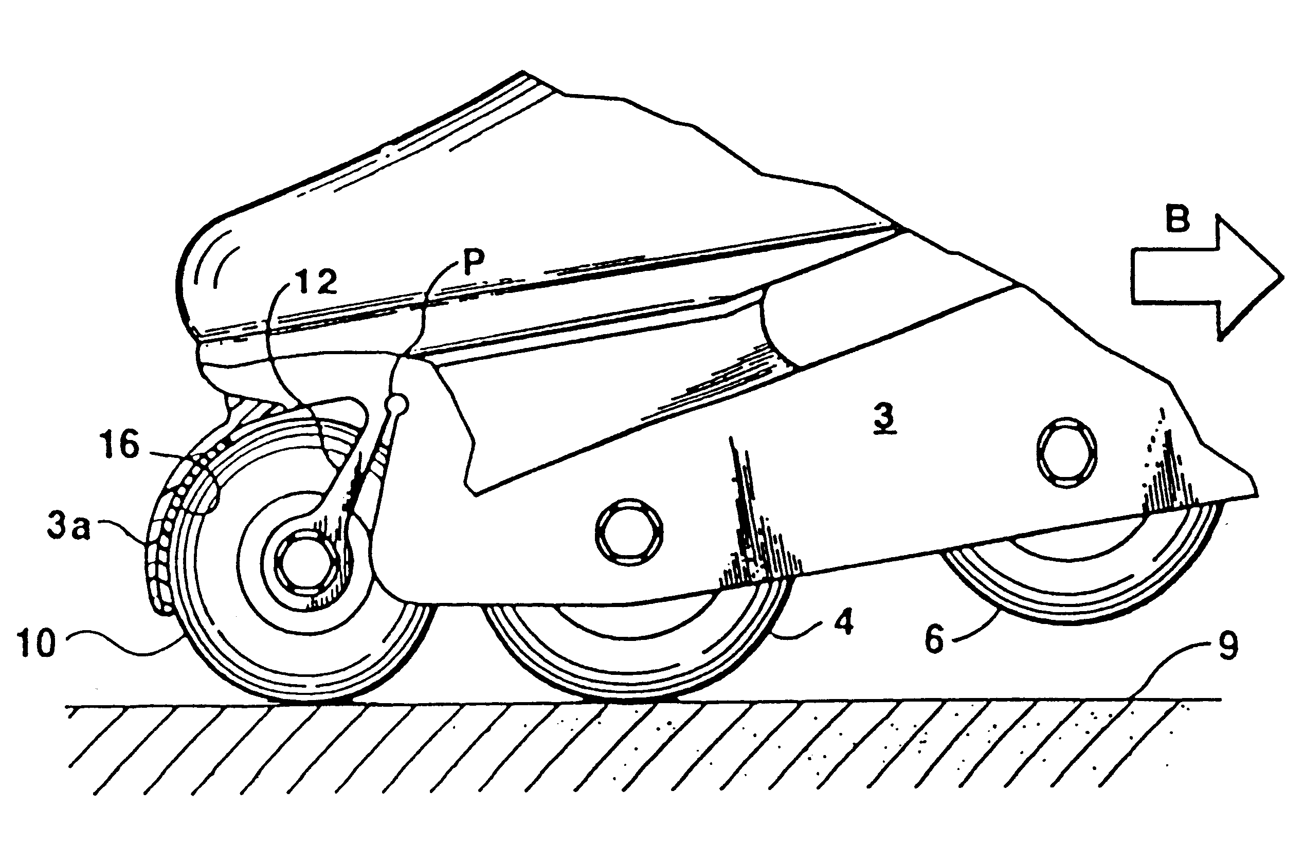
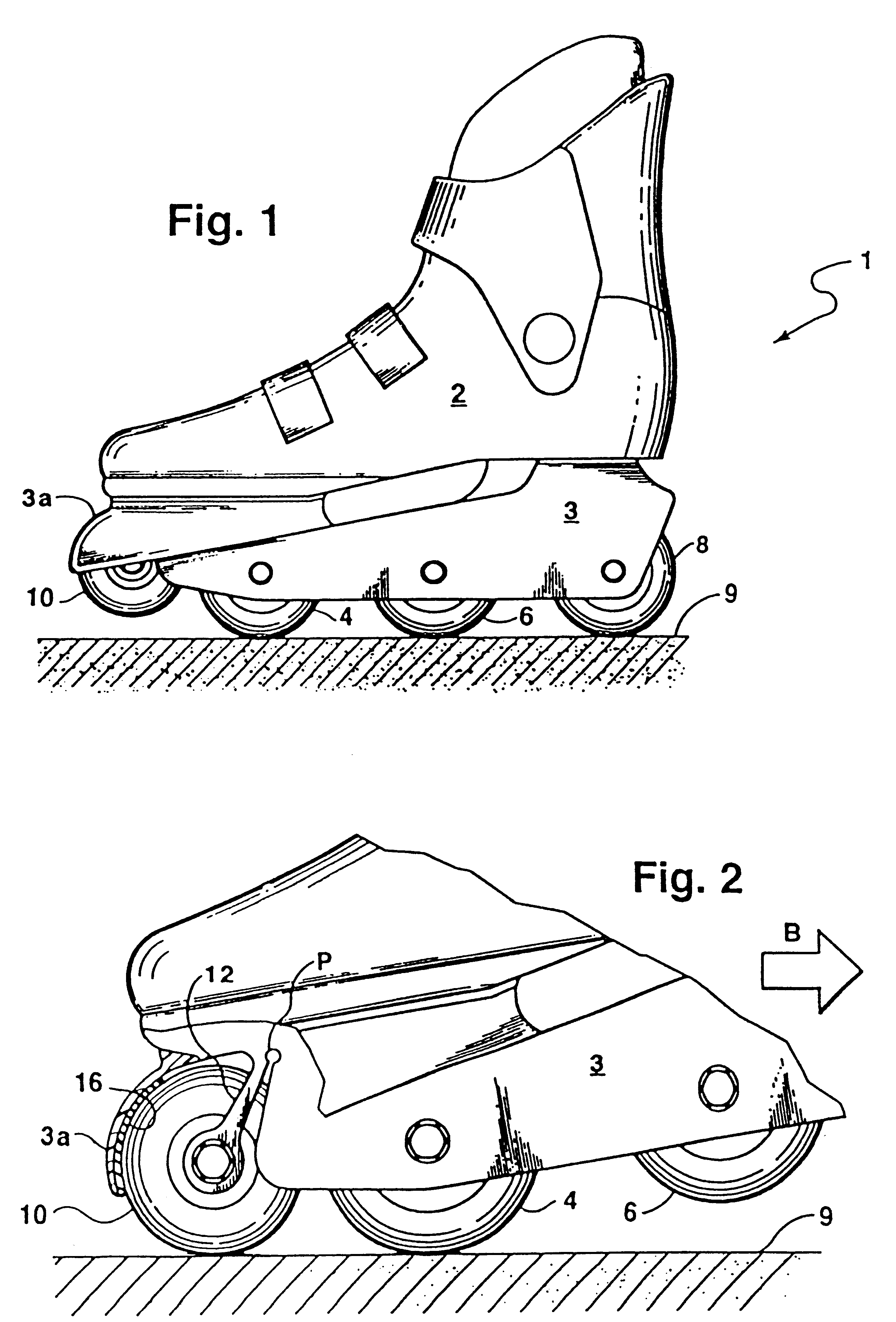
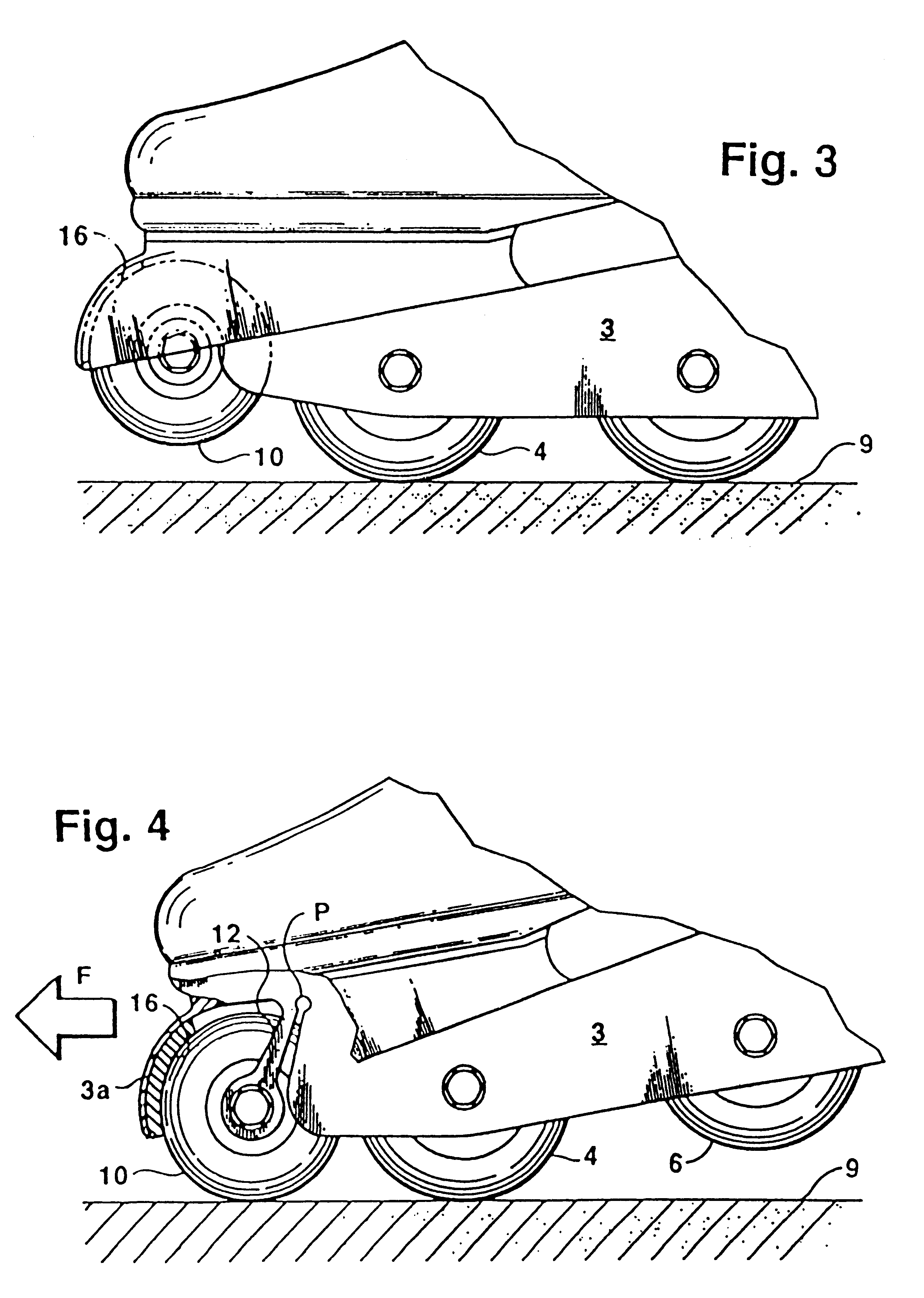
With reference to FIG. 1, a skate such as an in-line skate 1 has a boot 2, a skate frame 3 and three regular wheels 4, 6 and 8 mounted to the frame as is well known in the art. All three of these wheels have the same radius and their centers lie along a common line, such that all three wheels will engage skating surface 9 at the same time. T...


PUM


Abstract

A braking system preferably for an in-line skate includes a brake pad mounted to a forward end of a skate frame and an elevated front wheel attached to the skate frame by two pivot arms. The pivot arms are biased forward which is in a clockwise direction with respect to their pivot point. When skating normally, the pivot arms bias the wheel against the brake pad, but the wheel is elevated from the skating surface and thus the brake is not engaged. When skating in a rearward direction, or desiring a push start, the skater rotates the toe portion of the skate downward and raises the heel. The front wheel will engage the skating surface and the reaction force on the wheel due to friction between it and the skating surface which will urge the wheel forward and increase the contact pressure between it and the brake pad. When skating forward, if the skater rotates his or her foot so that the front wheel engages the skating surface, the frictional force between the surface and the wheel causes a rearward force on the wheel away from the brake pad, thus ensuring that the skater will not trip due to sudden braking of the front wheel.

Description

BACKGROUND OF TIME INVENTIONThe present invention relates to a brake for in-line skates, and in particular, to a front brake which is difficult to unintentionally actuate yet provides a reliable braking force.In-line skating has become increasingly popular. In many ways, it is similar to ice skating. Accordingly, playing hockey on in-line skates has also become popular. Standard in-line skates have a brake pad located at the heel of the skate. The brake is actuated by bending the knee of one leg and extending the other leg forward while rotating the toes upward and the heel downward as much as possible so that the brake will contact the ground. This is awkward for trying to stop or to hold one's ground against being pushed, or for obtaining a quick start. It is also awkward and potentially will trip the skater if used to stop while going backwards. While one can perform a T-stop, such a stop will damage the wheels and would be difficult to engage while moving backwards.It is also us...

Claims


Application Information

Patent Timeline
Patent Type & Authority Patents(United States)
IPC IPC(8): A63C17/00A63C17/14
CPCA63C17/1418A63C17/1445A63C17/06
Inventor HOLLAND, RONALD A.
Owner HEMISPHERE GROUP
Learn More