Apparatus for the method of testing vehicle

a technology for vehicles and apparatuses, applied in vehicle testing, apparatus for force/torque/work measurement, structure/machine measurement, etc., can solve problems such as not negligible influence factors

Inactive Publication Date: 2002-08-06
HITACHI PLANT TECH LTD
View PDF10 Cites 84 Cited by
  • Summary
  • Abstract
  • Description
  • Claims
  • Application Information

AI Technical Summary

Problems solved by technology

The variation in load and variation in the alignment for tires intricately influence upon each other so as to excessively affect the friction forces between the tires and the road surfaces, and cause influence factors which are not negligible for analyzing the maneuverability of the vehicle, in particular abrupt change in maneuvering.

Method used


Image

  • Apparatus for the method of testing vehicle
  • Apparatus for the method of testing vehicle
  • Apparatus for the method of testing vehicle

Examples


first embodiment

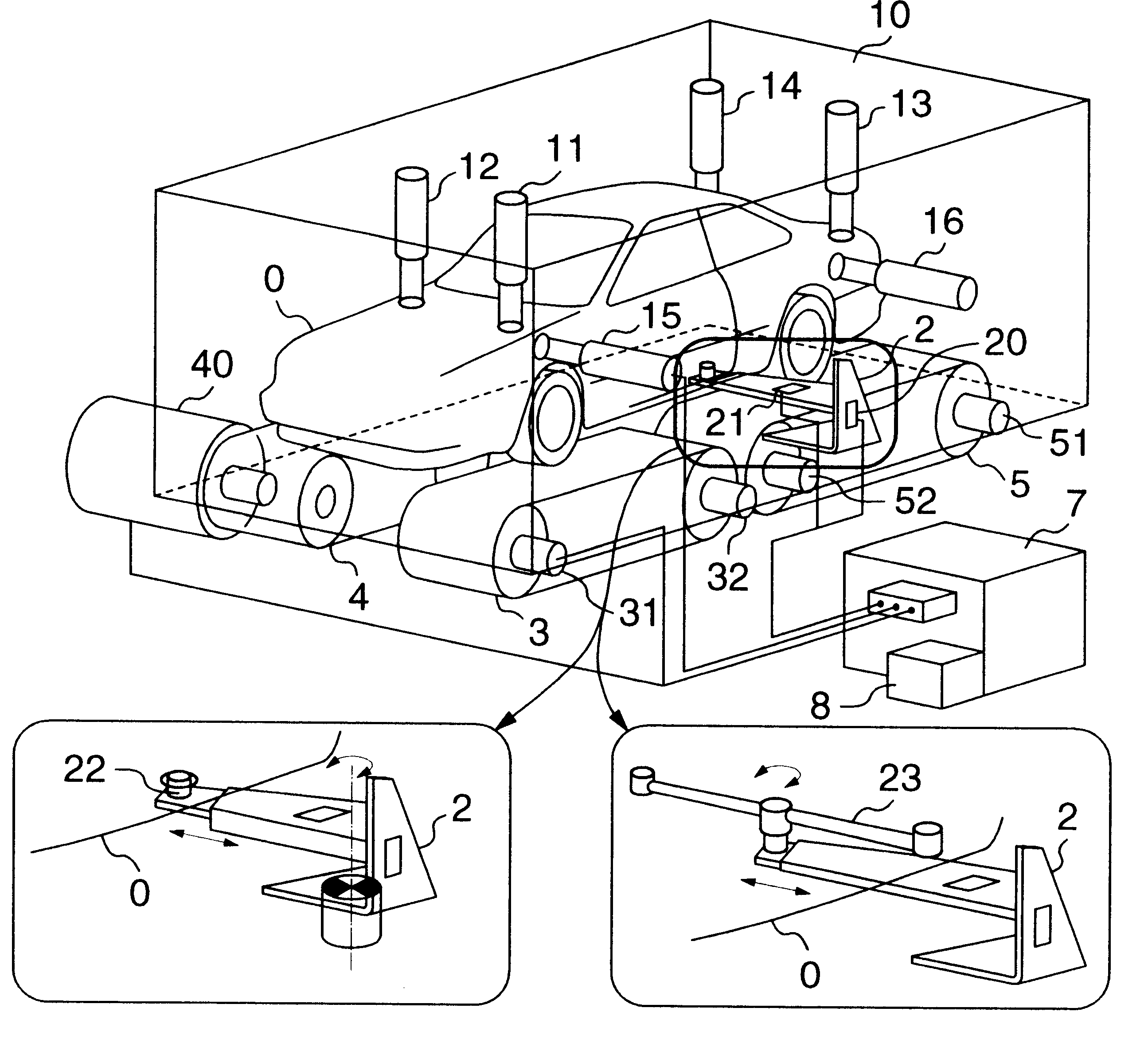
Referring at first FIG. 1a, the present invention will be explained.

A vehicle O is carried on a front left wheel flat belt 3, a front right wheel flat belt 4, a rear left wheel flat belt 5 and a rear right wheel flat belt 6 which serve as dummy load surface means used for a road surface. These flat belts are driven and braked by motor generators (only a motor generator 40 for the front right flat belt 4 is shown) for power generation for absorption. Further, although not shown, the flat belts may be carried on a test bench, or arranged on a base or a floor serving as a reference plane. In such a case that the flat belts are arranged on a base or a floor, these are preferably embedded therein.

The vehicle O is fixed to the frame 10 so as to arrest only a motion longitudinal of the vehicle by means of securing (arresting) members 2. That is, motions in the crosswise and vertical direction of the vehicle, pitching and rolling, and yawing can be produced with no restriction. Accordingly,...

second embodiment

Further, although, in this embodiment, the method in which the actuators are directly attached to the vehicle has been explained, a jig 9 may be provided to the vehicle in order to exert forces to the vehicle from the actuators, as will be explained later in the present invention shown in FIG. 11. With this arrangement, the points at which the actuators exert forces to the vehicle can be changed determined, irrespective of a shape of the vehicle, and accordingly, the drive can be made in a more ideal manner. Further, the freedom with which the actuators are attached to the jig 9 is higher than that of the arrangement in which the actuators are attached directly to the vehicle, thereby it is possible to reduce interference among the forces of the actuators.

third embodiment

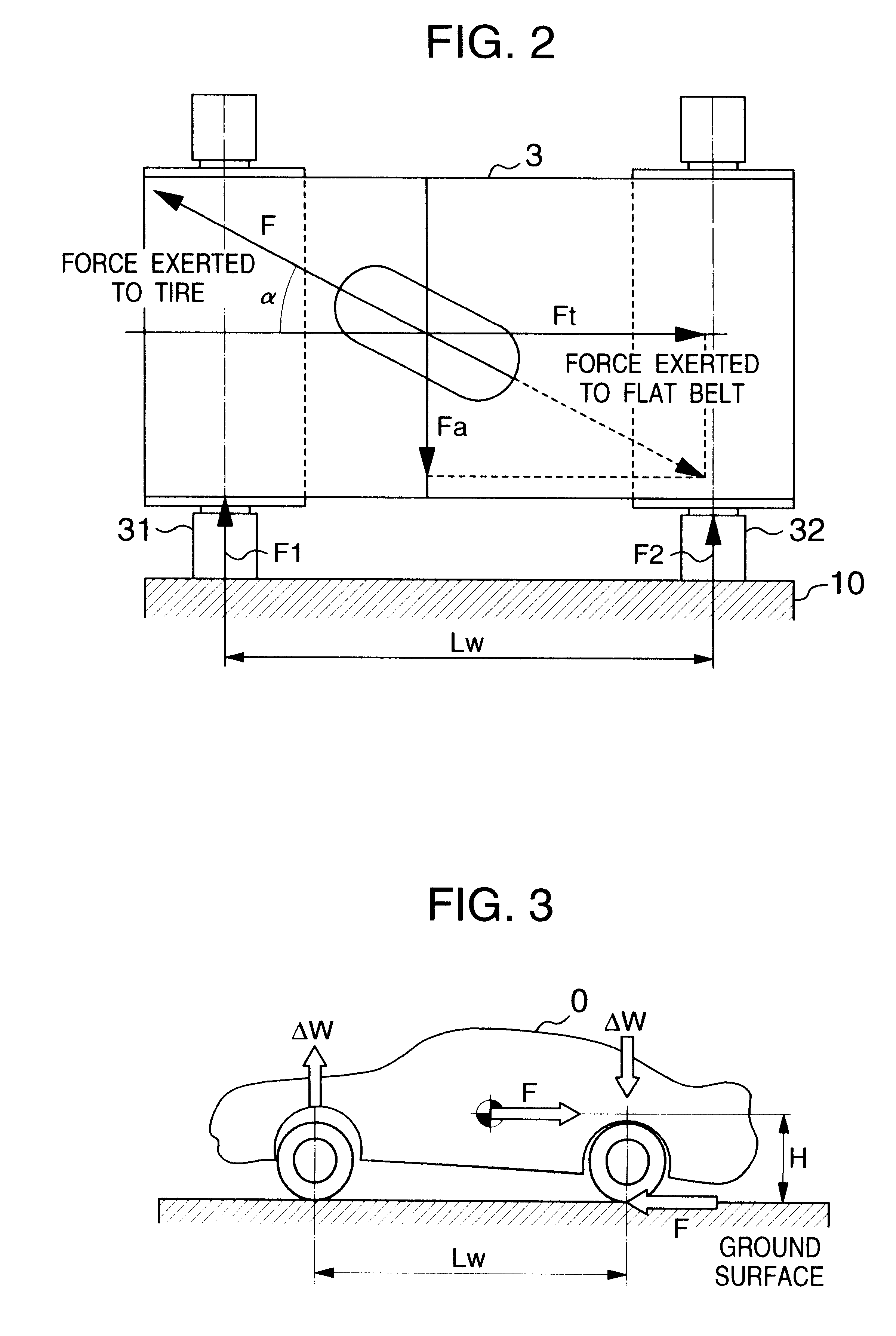
Further, as explained in a third embodiment shown in FIG. 12, rollers may be used as the dummy road surface means, instead of the flat belts. This arrangement using the rollers can be constituted by a low cost in comparison with the arrangement using the flat belts, and further, the control of the frictional coefficients of the outer surfaces of the roller can be easily made. However, in the arrangement using the rollers, the positioning of the rollers and the tires is difficult since it is likely that the ground contact conditions of the tires vary soon. In particular, it cannot cope with such a case condition that an angle is set between the roller axial direction and the vehicle crosswise direction (in a yawing occurring condition).

Further, although as shown in FIG. 2, the flat belts or the roller for four wheels are driven, independent from one another, in response to signals from the drive signal storage means 8, the left and right wheels may be linked together, for the sake of...


PUM

PropertyMeasurementUnit
force measuringaaaaaaaaaa
forceaaaaaaaaaa
forcesaaaaaaaaaa

Abstract

Provided is a vehicle testing apparatus which involves load variation and alignment variation, for analyzing a maneuverability of a vehicle on flat belts or rollers adapted to be rotated together with wheels of the vehicle, and in particular, maneuver variation. Load variation caused by an inertia force and a gravitational force which are produced during actual running of the vehicle, and tire alignment variation caused by suspension strokes, are forcibly reproduced by forces produced by actuators or a gravitational force, thereby it is possible to evaluate a maneuverability of the vehicle in a condition substantially the same as that during actual running of the vehicle.

Description

The present invention relates to an apparatus for and a method of testing the maneuverability of a vehicle on a test bench.RELATED ARTA flat belt type chassis dynamo is now proposed in order to evaluate the maneuvering stability of the vehicle, substituting for a conventional drum type chassis dynamo. For example, Japanese Patent Unexamined Publication No. 6-249753 discloses a method in which support parts are provided on the upper surfaces of movable parts which can be swung by first hydraulic jacks actuated independent from one another, and can be swung widthwise of the vehicle by second hydraulic jacks actuated independent from one another, corresponding to wheels of a vehicle, and flat belts making contact with the wheels of the vehicle are provided respectively to the support parts, the movable parts being inclined so as to reproduce a climbing slope and a ramp and the support parts being inclined so as to variously change ground contact conditions of the wheels of the vehicle ...

Claims


Application Information

Patent Timeline
Patent Type & Authority Patents(United States)
IPC IPC(8): G01M17/04G01M17/06G01M17/007
CPCG01M17/0072G01M17/0074G01M17/045G01M17/065
Inventor YAMAKADO, MAKOTOHORIUCHI, TOSHIHIKOKONNO, TAKAO
Owner HITACHI PLANT TECH LTD
Why Eureka
Try Eureka