
Adhesive applicator tips with improved flow properties

Inactive Publication Date: 2002-08-06
ETHICON INC
View PDF64 Cites 29 Cited by
  • Summary
  • Abstract
  • Description
  • Claims
  • Application Information

AI Technical Summary

Problems solved by technology

However, with the application of adhesive in its monomeric form, due to the rapid polymerization rate of the monomers, it has been challenging to design effective and commercially viable packaging and dispensing systems.
However, a problem with many of these applicator systems is that the product contains more adhesive material than is necessary for a particular use.
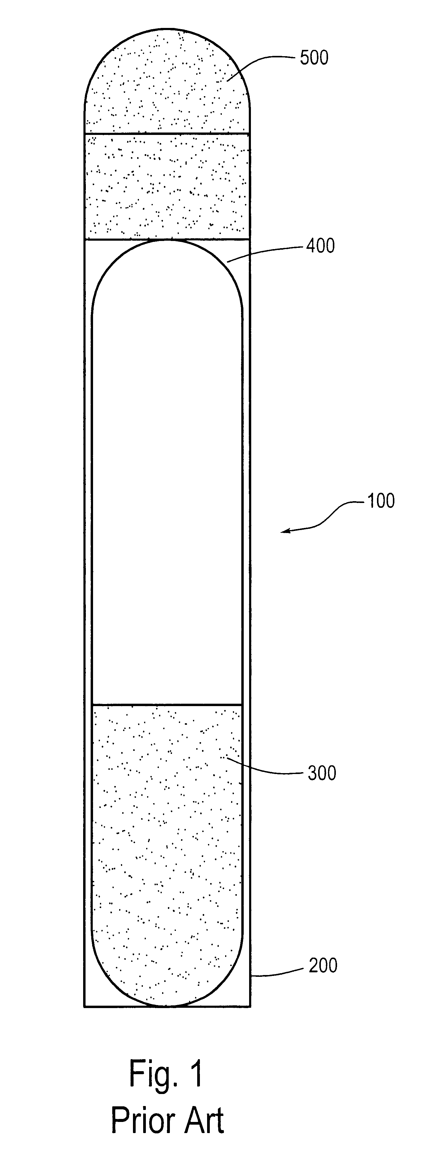
A disadvantage of some known applicator systems, and particularly applicators containing a frangible vial and a porous applicator tip for expelling the adhesive, is that monomer material may be wasted by filling the pores of the applicator tip in areas other than the areas used to apply the adhesive.
Furthermore, some known applicator tips suffer from the problem of the monomer being expelled through the entire surface area of the tip, and even to greater extents in areas other than the area used to apply the monomer to the desired substrate.
This leads to a further problem of less precise control over the area of application of the monomer to the substrate.
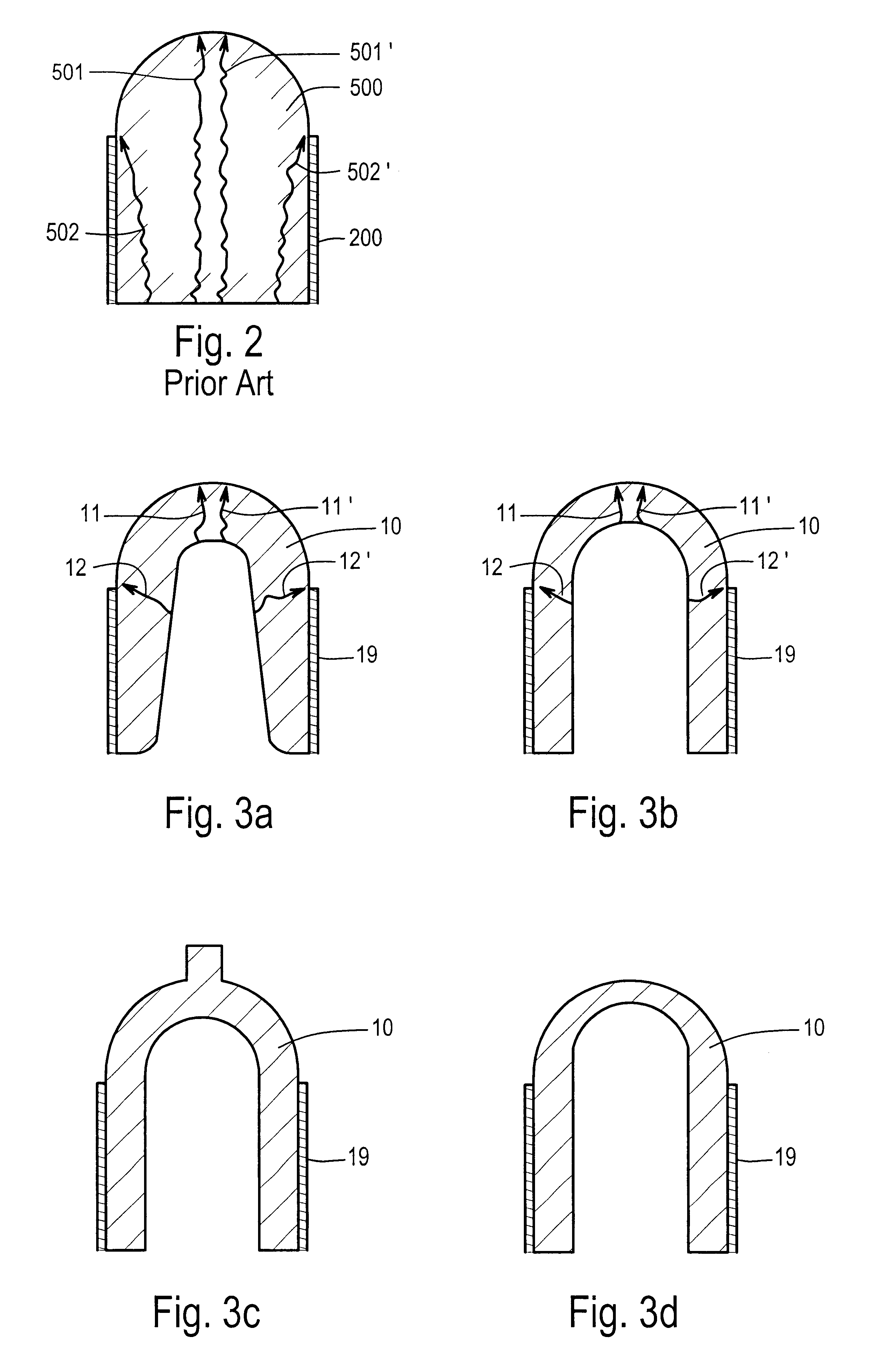
However, a difficulty encountered with such a dome-shaped applicator tip, as well as with other solid applicator tips, is that the monomeric adhesive material being expelled through the applicator tip tends to follow paths of least resistance within the tip.
Because the end of the tip is desired to be used to apply the adhesive, less precise control of placement of the adhesive is obtained because adhesive becomes expelled through the entire surface of the tip.
This also tends to result in waste of adhesive material, because all of the adhesive does not exit from the tip at the same location.
However, the compositions within the crushable ampoules are, in both products, adhesive activators, not the adhesive composition itself.
In this product also, the above-described problems of wasted material (here, initiator) and less precision in application are also present.

Method used


Image

  • Adhesive applicator tips with improved flow properties
  • Adhesive applicator tips with improved flow properties
  • Adhesive applicator tips with improved flow properties

Examples


Embodiment Construction

The present invention provides improved applicator tips and applicator devices that provide significant improvement in the application and use of adhesive material. Such applicator tips can be used, for example, in combination with the adhesive compositions and packaging and dispensing systems set forth in U.S. Pat. No. 5,928,611, the entire disclosure of which is incorporated herein by reference. Of course, other adhesive compositions, compatible with the applicators of the present invention, can also be used.

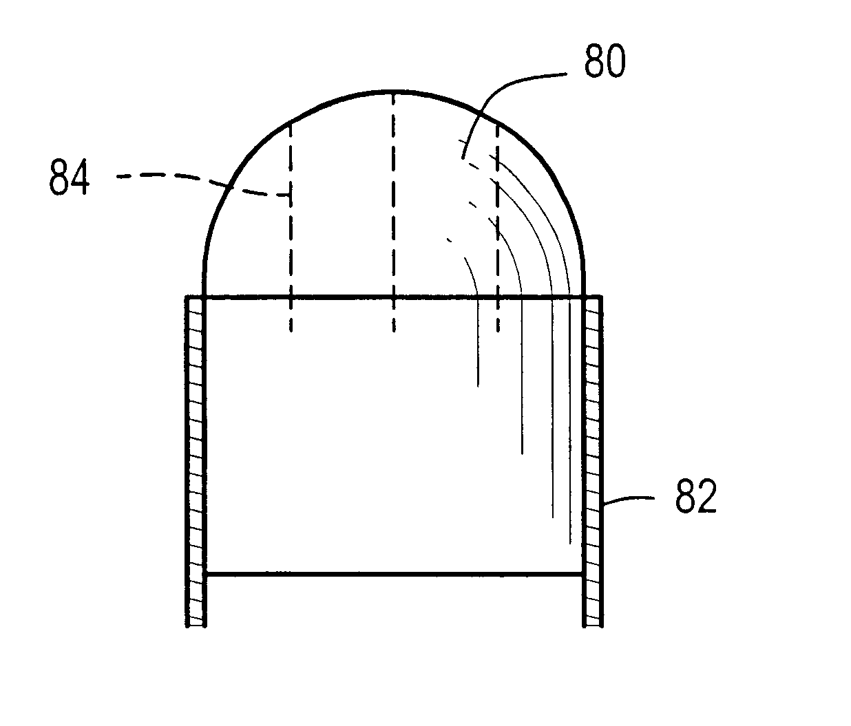
In embodiments of the present invention, an improved applicator tip is provided wherein the shape and / or construction of the applicator tip is selected so as to control the flow pattern of the adhesive through and / or on the applicator tip. For example, the shape of the applicator tip can be selected so as to control the flow paths of the adhesive material, or the surface of the applicator tip can be configured to channel adhesive material exiting the applicator tip to a predet...


PUM


Abstract

An article of manufacture for dispensing an adhesive material, such as a synthetic or semi-synthetic polymerizable or cross-linkable monomer material, includes a container body, and a porous applicator tip having a proximal end that is attached to the container body, and a distal end located away from the container body, wherein the adhesive material is located in the container body in a non-contacting relationship with the applicator tip prior to dispensing the material. A flow pattern of the adhesive material within or on the applicator tip is controlled by providing one or more cuts in the applicator tip to alter flow properties of the adhesive material through the applicator tip.

Description

1. Field of the InventionThis invention relates to an improved design for an applicator tip, particularly for use with an applicator that dispenses adhesive material. In particular, the present invention relates to an applicator tip that exhibits an improved flow pattern of the adhesive material in or through the applicator tip, which allows for more precise placement of the adhesive material and decreased waste of adhesive material.2. Description of Related ArtMonomer and polymer adhesives are used in both industrial (including household) and medical applications. Included among these adhesives are the 1,1-disubstituted ethylene monomers and polymers, such as the .alpha.-cyanoacrylates. Since the discovery of the adhesive properties of such monomers and polymers, they have found wide use due to the speed with which they cure, the strength of the resulting bond formed, and their relative ease of use. These characteristics have made the .alpha.-cyanoacrylate adhesives the primary cho...

Claims


Application Information

Patent Timeline
IPC IPC(8): A61B17/00B05C17/00B65D83/00B05D1/26B05D7/00B05D7/24
CPCA61B17/00491B05C17/002
Inventor BOBO, JOHNBRADY, MICHAEL F.CLARK, JEFFREY G.COTTER, WILLIAM M.HEDGPETH, DANIEL L.HICKEY, TIMOTHY P.JONN, JERRYMOSELEY, JONQUINTERO, JULIAN
Owner ETHICON INC
Learn More