Air supply pressure regulator with supply tank pressure gauge and air supply port

a pressure regulator and air supply technology, applied in the direction of fluid pressure control, underwater equipment, instruments, etc., can solve the problems of scuba diving equipment life-threatening consequences, extreme equipment dependence, and direct proportional cost of scuba diving equipment to thousands of users

Inactive Publication Date: 2002-08-20
DANA J SCHWARTZ MONEY PURCHASE PLAN
View PDF8 Cites 16 Cited by
  • Summary
  • Abstract
  • Description
  • Claims
  • Application Information

AI Technical Summary

Benefits of technology

FIG. 6 is an exterior perspective view of the digitally gauged embodiment of the buoyancy control unit herein disclosed.
FIG. 7 is a cut away side view of the digitally gauged embodiment of the buoyancy control unit herein disclosed.

Problems solved by technology

Scuba diving the world over, whether it be A commercial endeavor or for sport diving, is extremely equipment dependent.
The quality and performance of the scuba-diving equipment not only affect the quality of the underwater experience, such equipment has life threatening consequences should it malfunction or be confusing to operate to a dazed or inexperienced diver.
Further, the cost of scuba-diving equipment to thousands of users is directly proportional to the number of parts that must be interconnected on the tank and hose apparatus used for diving.
As is obvious, the number of hoses dangling from the scuba diver during a dive is cumbersome.
Danger from such hoses is also encountered while swimming through dense kelp beds which have a natural propensity to wrap around such hose lines and entangling them and the diver.
Further, pressure gauges now conventionally attached to the distal end of a high pressure hose inhibit an easy and constant monitoring of remaining air by the diver.
Such a nuisance not only makes for a diver that is less diligent about monitoring remaining air, it also wastes the valuable breathable air supply due to increased body movement.
Such increases are necessitated by the interruption of the diver's gliding in the water and excess swimming strokes caused by the need to stop, tread water, and grope for the gauge to view it.
Prior art has attempted to address some of the aforementioned problems but without great success.
However, Isaacon does not address the issue of placing the tank pressure gauge in easy eyesight of the user nor does Isaacson address the issue of the buoyancy compensating using for a diver.
U.S. Pat. No. 4,449,524 (Gray) provides for the attachment of a second breathing apparatus to a regulator but fails to address the issue of a continually visible pressure gauge and user operable inflation valve.
Other art teaches various devices for use with breathing apparatus attached to pressurized air tanks, but none address the removing the dangers of multiple hoses or providing an easily viewed high pressure tank gauge to monitor remaining the remaining air supply.

Method used


Image

  • Air supply pressure regulator with supply tank pressure gauge and air supply port
  • Air supply pressure regulator with supply tank pressure gauge and air supply port
  • Air supply pressure regulator with supply tank pressure gauge and air supply port

Examples


Embodiment Construction

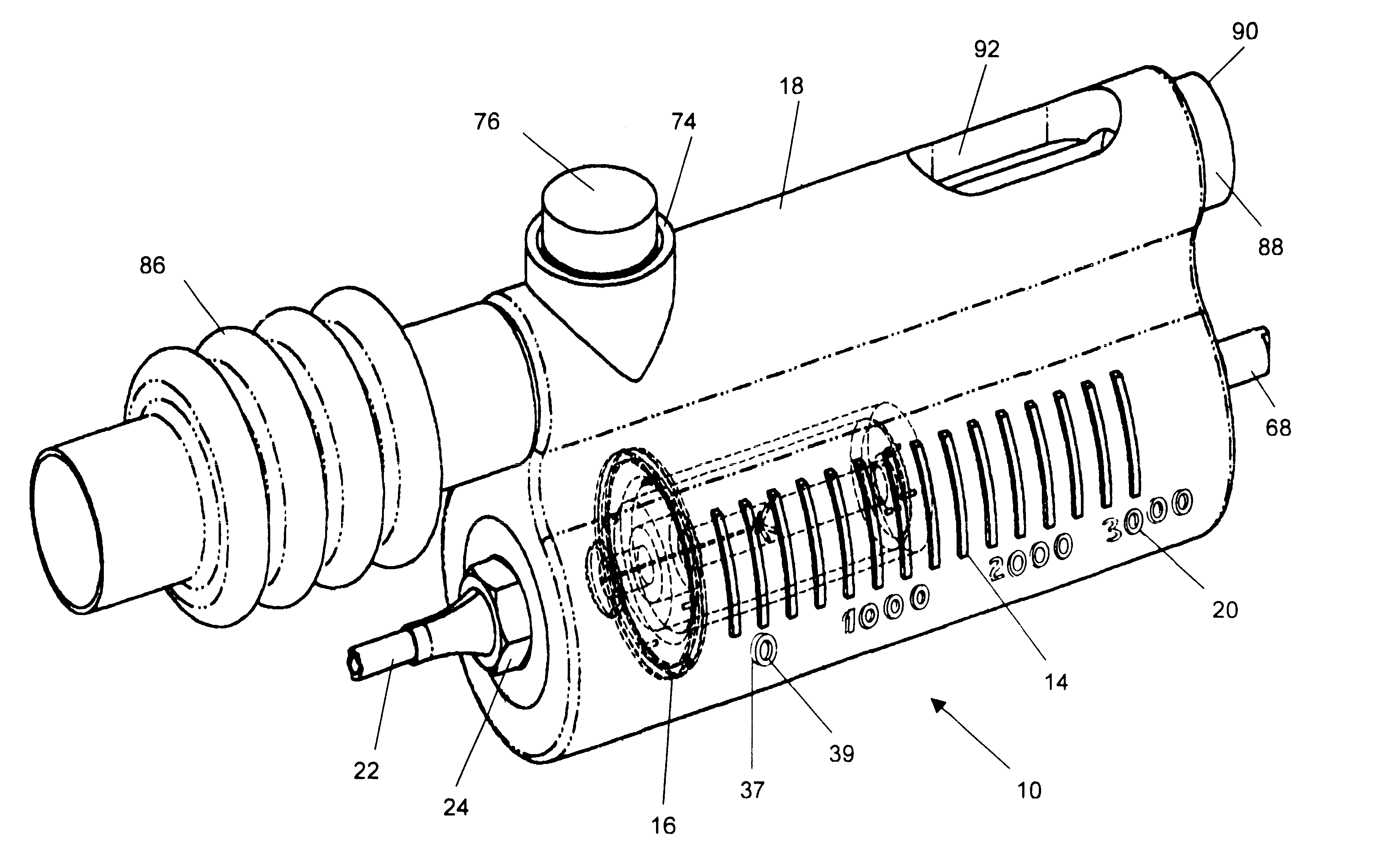
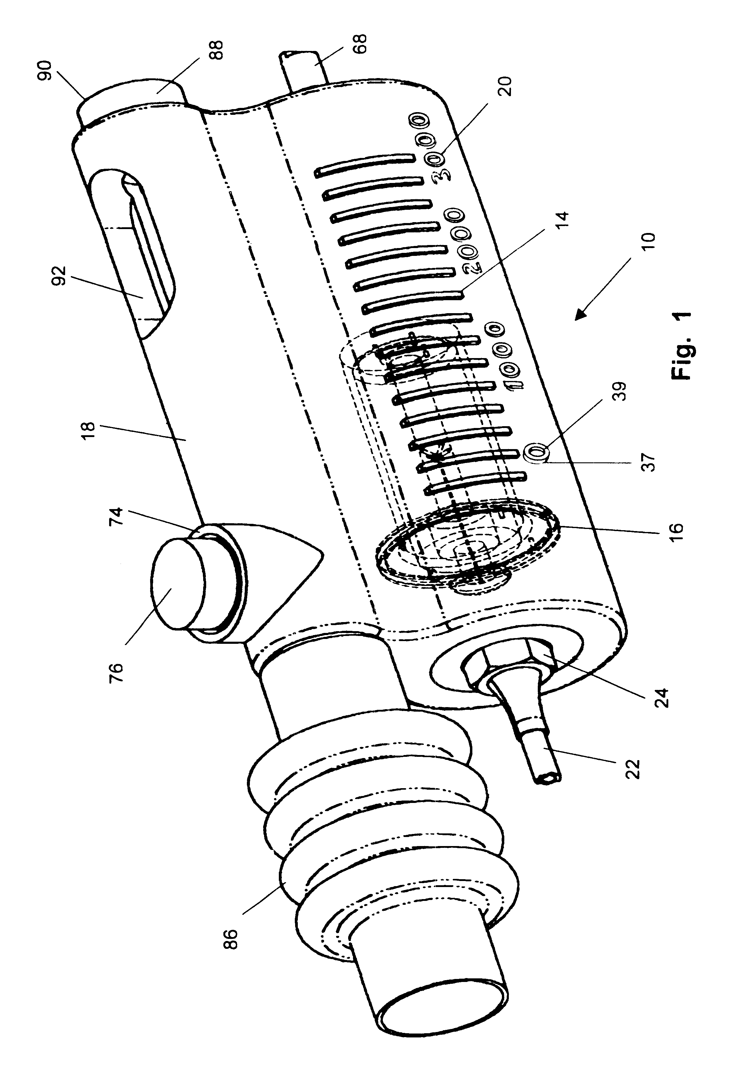
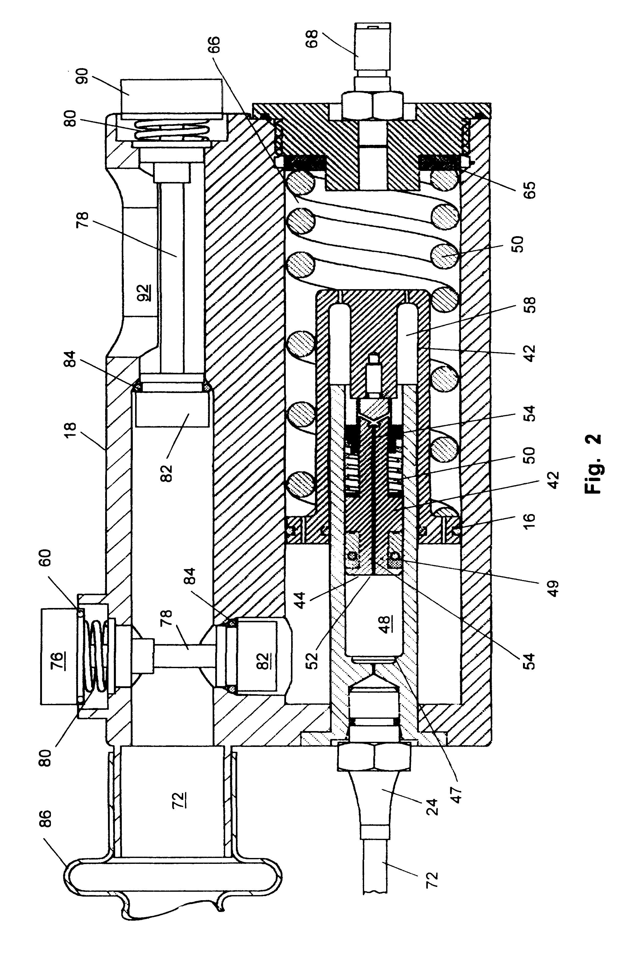
Referring now to the drawing FIGS. 1-7, specifically FIG. 1 and FIG. 2 disclose a preferred embodiment of the disclosed buoyancy control unit 10 featuring a reciprocating means to determine remaining supply tank pressure in the form of a mechanically operated pressure gauge 12 which when attached to a scuba tank to be used in combination herewith, will display a reading of remaining tank pressure in the tank. The mechanical pressure gauge 11 is provided by the functional relationship of transparent slots 14 or other markings to show lateral translation, located in the side of control body 18 which are arranged parallel to each other in a linear fashion much like a thermometer. Indicia 20, calculated to indicate relative tank pressure of the communicating tank for use in combination with the device herein disclosed, is placed in appropriate positions adjacent to the appropriate slots 14 thereby yielding a pressure gauge 11 when viewed in combination with markings visible through the ...


PUM

PropertyMeasurementUnit
pressureaaaaaaaaaa
pressureaaaaaaaaaa
pressureaaaaaaaaaa

Abstract

An improved regulating and gauging device for attachment to tank fed breathing apparatus used in such endeavors as scuba diving or fire fighting. On the body of the device are components which concurrently function to provide the diver or other user with a single source for what are conventionally, multiple components of a pressure gauge, a regulator, and a buoyancy compensating control unit. The device has mounted in or upon the device body, a mechanical or digital display of the remaining tank pressure in the attached supply tank, and thus breathable air supply. Also provided are an outlet to a buoyancy control bag, and a quick connect air supply port for another person to use in emergencies, or as needed. Additional utility is achieved by the provision of the pressure gauge which is mounted upon the exterior buoyancy compensating control unit body where the user can easily see it during use. Optionally a microprocessor fitted with software to calculate and display real time remaining air supply based on current usage levels may be provided when used with a digital electronic gauge.

Description

BACKGROUND OF INVENTION1. Field of InventionThe present invention relates to equipment for use with self contained underwater breathing apparatus (Scuba). More particularly, it relates to an improved buoyancy compensator controlling unit, which communicates directly with the high pressure of a supply tank, and has a supply tank pressure gauge and selectively accessible air supply port on the same unitary structure.2. Prior ArtScuba diving the world over, whether it be A commercial endeavor or for sport diving, is extremely equipment dependent. The quality and performance of the scuba-diving equipment not only affect the quality of the underwater experience, such equipment has life threatening consequences should it malfunction or be confusing to operate to a dazed or inexperienced diver. Further, the cost of scuba-diving equipment to thousands of users is directly proportional to the number of parts that must be interconnected on the tank and hose apparatus used for diving.The embod...

Claims


Application Information

Patent Timeline
Patent Type & Authority Patents(United States)
IPC IPC(8): A62B9/02A62B9/00B63C11/22B63C11/02G05D16/10G05D16/04
CPCA62B9/006A62B9/02B63C11/2245G05D16/103B63C2011/021B63C2011/188G05D16/106
Inventor HOLLOWAY, ROCCOMINICH, ROGER
Owner DANA J SCHWARTZ MONEY PURCHASE PLAN
Why Eureka
Try Eureka