
LED wayside signal for a railway

a technology of wayside signal and led lamp, which is applied in the direction of railway signalling, traffic crossing safety means, transportation and packaging, etc., can solve the problems of inconvenient and time-consuming replacement of burned out wayside signal by maintenance personnel, short life of incandescent lamps, and particularly problematic problems

Inactive Publication Date: 2002-08-20
DIALIGHT CORP
View PDF7 Cites 57 Cited by
  • Summary
  • Abstract
  • Description
  • Claims
  • Application Information

AI Technical Summary

Problems solved by technology

However, the use of incandescent lamps in the wayside signals results in certain drawbacks.
First, the life of incandescent lamps is relatively short, i.e., an incandescent lamp typically burns out in a relatively short period of time of approximately 6 to 12 months.
This may be particularly problematic in wayside signals for railways as such wayside signals may often be placed at remote locations along railroad tracks.
As a result, it is often inconvenient and time consuming for maintenance personnel to replace a burned out wayside signal.
Also, any time a wayside signal burns out safety concerns are raised and the use of certain railroad track sections may be prohibited, resulting in a loss of operating efficiency, requiring track reroutings, etc.
A further drawback with wayside signals utilizing incandescent lamps is that they are relatively energy inefficient.

Method used


Image

  • LED wayside signal for a railway
  • LED wayside signal for a railway
  • LED wayside signal for a railway

Examples


Embodiment Construction

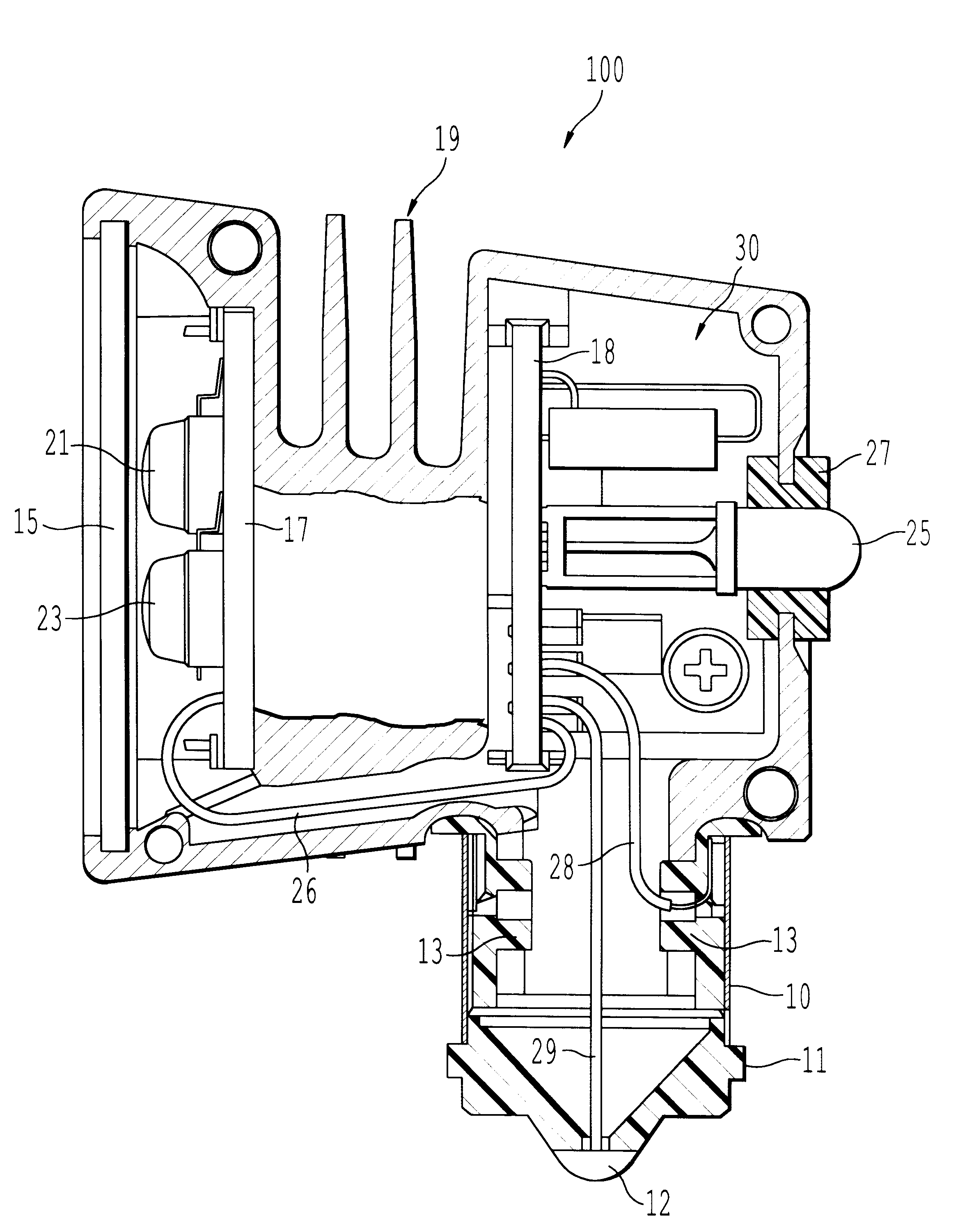
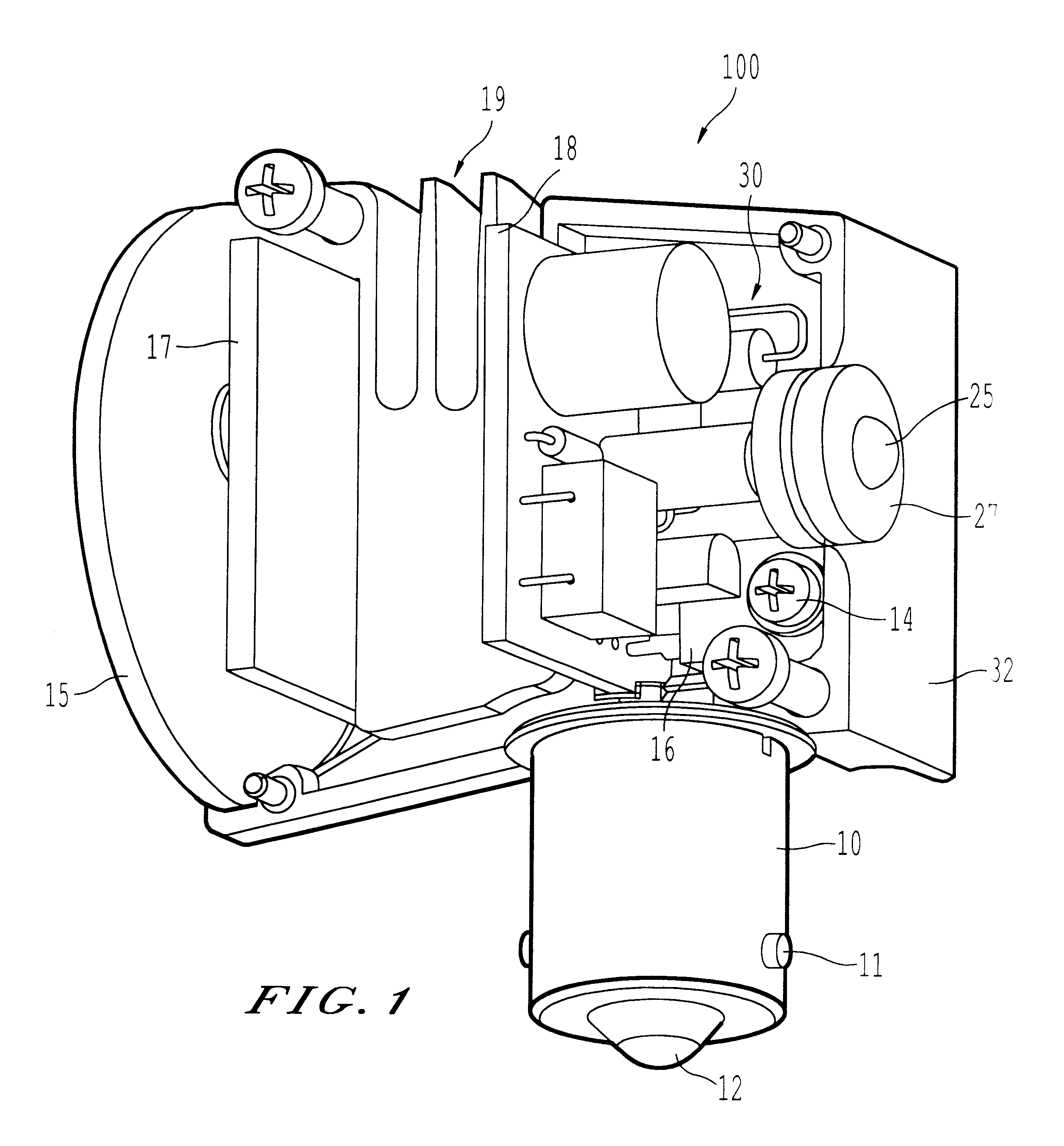
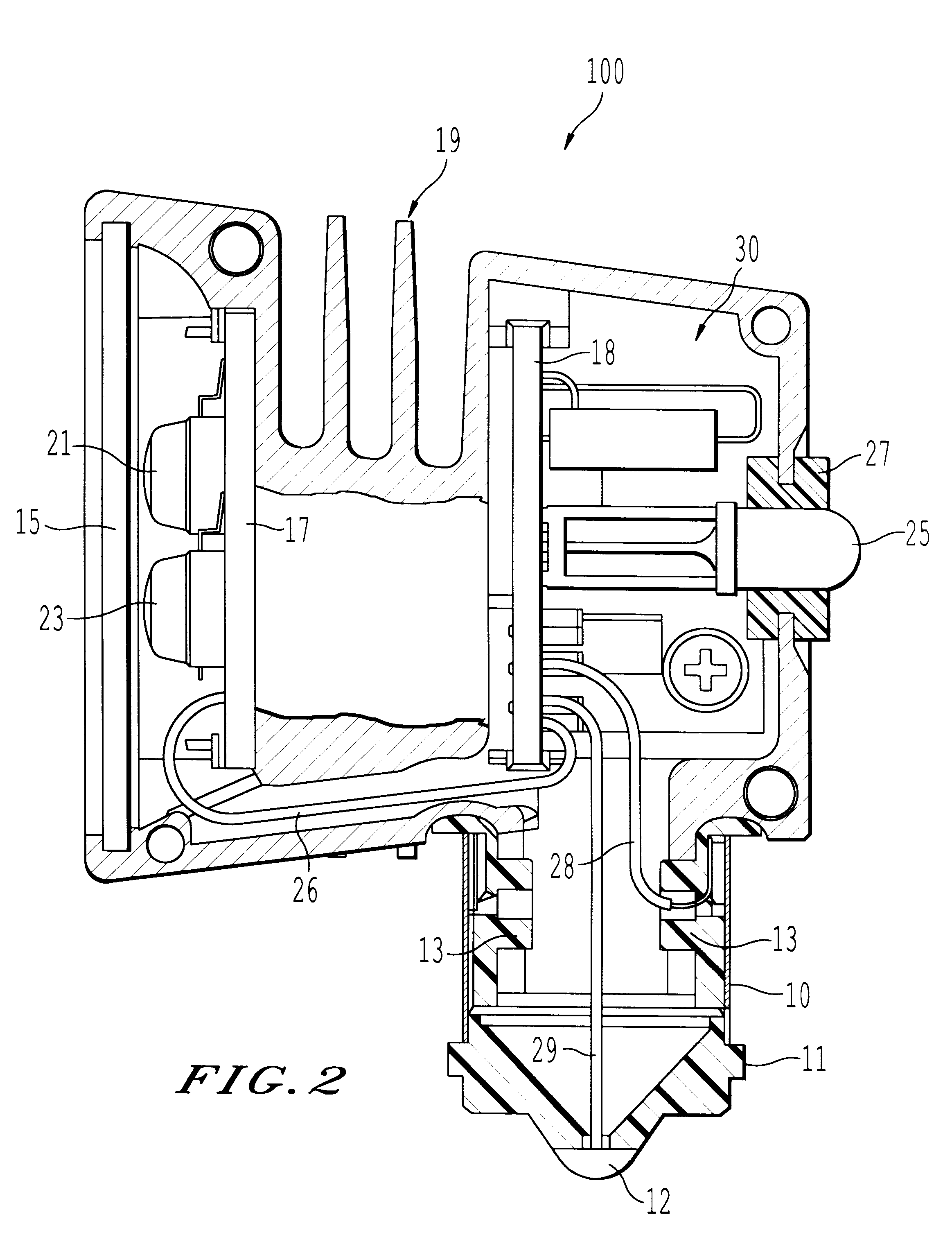
Referring now to the drawings, wherein like reference numerals designate identical or corresponding parts throughout the several views, and more particularly to FIGS. 1 and 2 thereof, perspective internal and cut-out side views of the wayside signal of the present invention are provided.

As shown in FIGS. 1 and 2, the wayside signal 100 of the present invention includes a front lens 15 which covers two LED elements 21 and 23. FIGS. 1 and 2 show two LED elements 21 and 23, although different numbers of LED elements may be used. The LED elements 21 and 23 may be of the same or different colors. For example, the LED elements 21, 23 may each be red LEDs. As one possible alternative, multiple color LEDs could be utilized. As an example, red and yellow LEDs could be utilized to obtain an orange output light, or reverse mounted green and red LEDs may be utilized such that the green LED is opposite a forward mounted red LED so that by applying a voltage of a first polarity to the LEDs the LE...


PUM


Abstract

A wayside signal for a railway includes a plurality of light emitting diodes housed in a housing. The light emitting diodes output indication signals. Further, the light emitting diodes are configured on a first circuit board which is thermally coupled to the housing. The housing may also include heat sink fins to dissipate heat generated by the light emitting diodes and associated driving circuitry for driving the light emitting diodes also contained within the housing. An additional light emitting diode may also be contained within the housing to point in an opposite direction than the indication signal light emitting diodes, which additional light emitting diode may be formed on a second circuit board with the driving circuitry. The additional light emitting diode provides an indication to anyone behind the wayside signal as to the indication of the wayside signal. The wayside signal is further optimized for thermal efficiency and to be sealed against the elements. In regard to thermal efficiency, the first circuit board may be metal clad and the housing may be formed of black anodized aluminum. Also, a plastic insulator may be attached to the housing and covered with a lamp base. The lamp base may be configured to be inserted into a conventional socket for a wayside signal, so that the wayside signal of the present invention can be utilized with existing circuitry.

Description

1. Field of the InventionThe present invention is directed to an LED (light emitting diode) lamp which finds particular use as a wayside signal for a railway.2. Discussion of the BackgroundThe railroad industry utilizes wayside signals to indicate authorization for trains to proceed or to stop at certain positions on railroad tracks. Currently, such wayside signals utilize incandescent lamps to provide the indication for the train to proceed or not.However, the use of incandescent lamps in the wayside signals results in certain drawbacks. First, the life of incandescent lamps is relatively short, i.e., an incandescent lamp typically burns out in a relatively short period of time of approximately 6 to 12 months. This may be particularly problematic in wayside signals for railways as such wayside signals may often be placed at remote locations along railroad tracks. As a result, it is often inconvenient and time consuming for maintenance personnel to replace a burned out wayside signa...

Claims


Application Information

Patent Timeline
IPC IPC(8): B61L5/00B61L5/18
CPCB61L5/1827B61L2207/02
Inventor SANDERSON, JOHN RICHARDOESTERHELD, KLAUSEIKELBERGER, RAND
Owner DIALIGHT CORP
Learn More