
Continuously variable transmission

Inactive Publication Date: 2002-08-20
LUK LAMELLEN & KUPPLUNGSBAU BETEILIGUNGS KG +1
View PDF23 Cites 65 Cited by
  • Summary
  • Abstract
  • Description
  • Claims
  • Application Information

AI Technical Summary

Benefits of technology

An object of the present invention is to provide a transmission wherein an endless flexible element (such as a chain) is less likely to generate noise and / or to cause pronounced or excessive wear than the endless flexible elements in presently known continuously variable transmissions.
The cost of the guide can be reduced, at least slightly, by assembling the guide of two sections which are mirror images of each other and which are thereupon bonded and / or otherwise (such as mechanically) fastened to each other.

Problems solved by technology

Such undesirable side effect is attributable primarily to at least one of the elongated portions (known as stretches or reaches) of an endless flexible chain which is trained over at least two rotary members.
Such vibrations are undesirable for numerous reasons.
For example, if the vibrations are conveyed or communicated to the chassis of the motor vehicle, this can result in the generation of often readily detectable noise which is unpleasant to the driver as well as to other occupant(s) of the vehicle.
Furthermore, vibrations cause extensive wear, e.g., upon the links and / or pintles and / or other constituents of the chain, i.e., they can unduly affect the useful life of the chain and of the entire transmission.

Method used


Image

  • Continuously variable transmission
  • Continuously variable transmission
  • Continuously variable transmission

Examples


Embodiment Construction

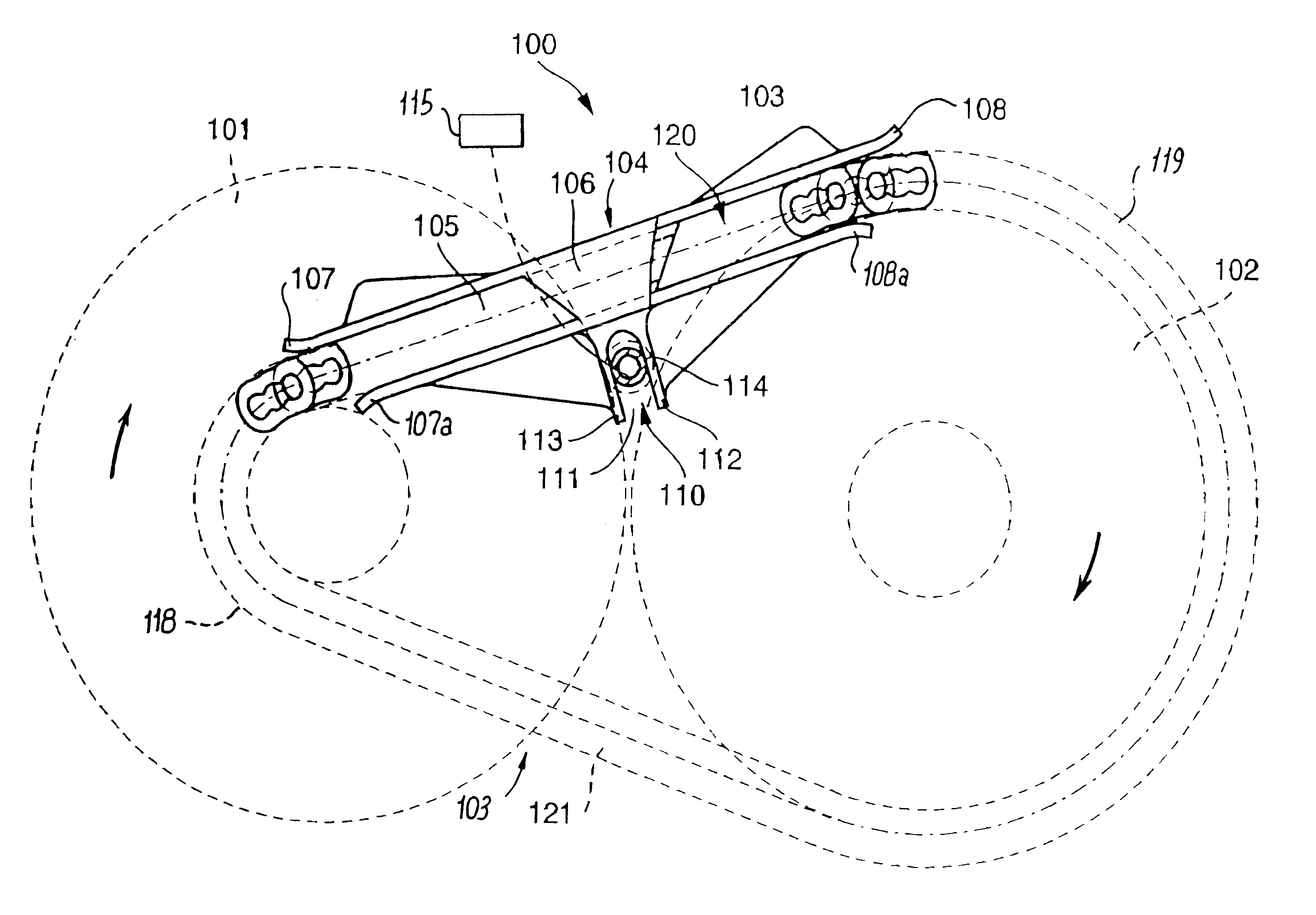
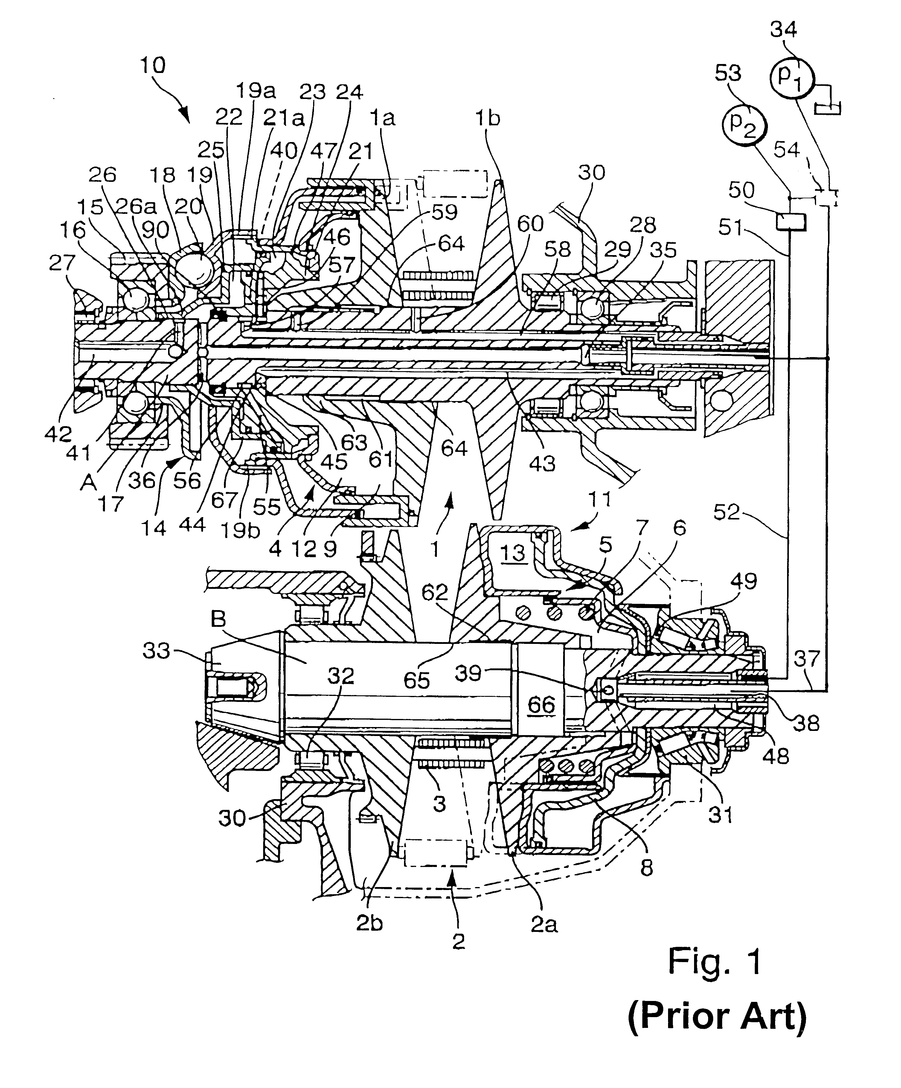
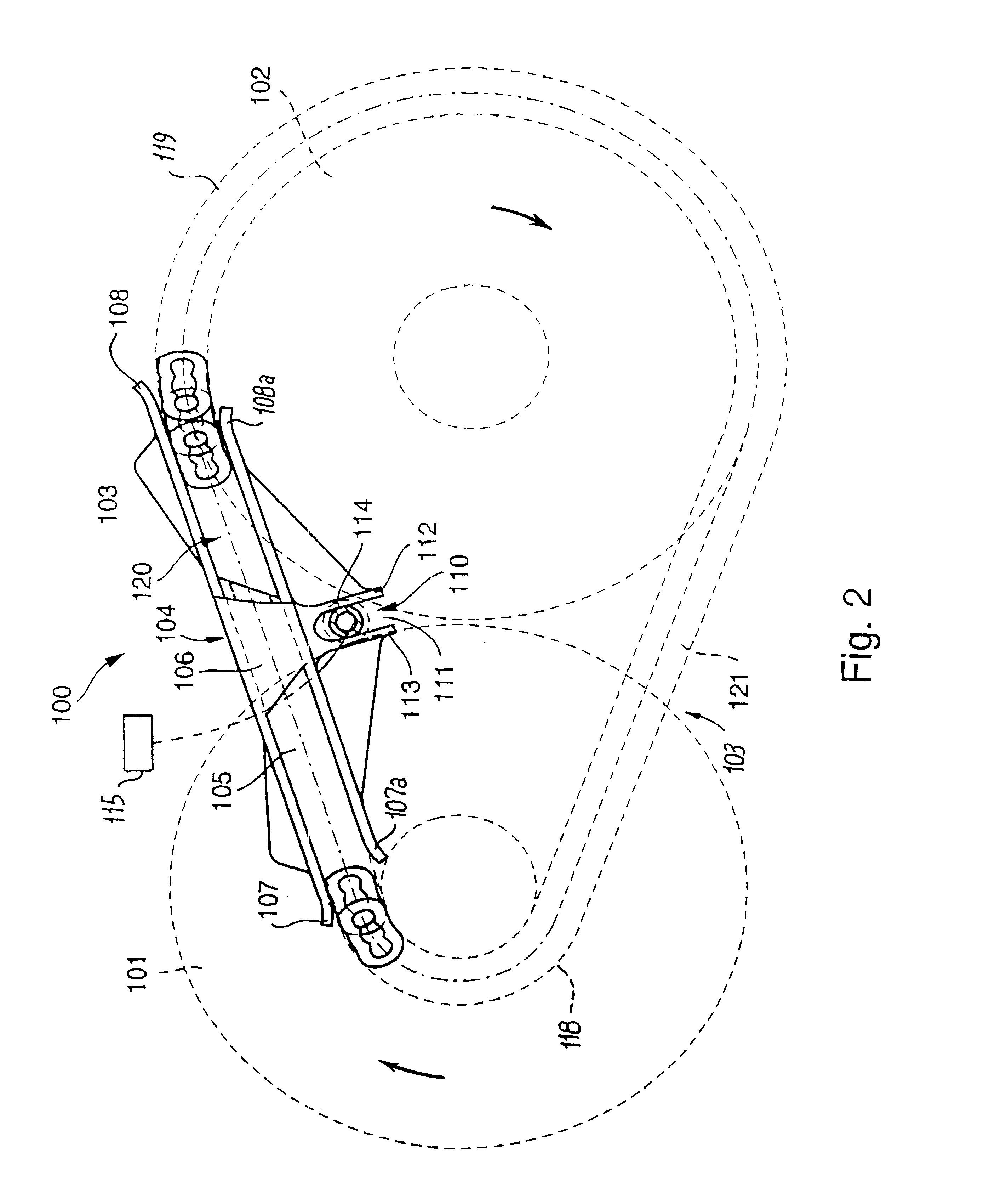
FIG. 1 shows certain relevant features of a power train of the type shown in FIGS. 1 and 1a of commonly owned U.S. Pat. No. 5,711,730 granted Jan. 27, 1998 to Oswald Friedmann et al. for "TORQUE MONITORING APPARATUS". The patented power train can employ an infinitely variable transmission (such as a continuously variable transmission known as CVT) wherein an endless flexible. torque transmitting element (such as a link chain or pintle chain) can be utilized jointly with a guide which is designed and incorporated into the transmission in accordance with the present invention.

Referring now to FIG. 1 in detail, there is shown an infinitely variable transmission including a first rotary member 1 constituting an adjustable sheave or pulley, a second rotary member 2 also constituting an adjustable sheave or pulley, and an endless flexible element 3 (e.g., a chain). The flexible element 3 (herein-after called chain for short) includes first and second arcuate portions which are respectivel...


PUM


Abstract

A continuously variable transmission or an analogous torque transmitting system has two rotary members in the form of wheels, gears or pulleys (such as adjustable pulleys) which are rotatable about parallel axes. An endless flexible element in the form of a link chain, pintle chain or belt has arcuate portions trained over the rotary members and elongated reaches or stretches extending between the arcuate portions. At least one of the stretches is at least partially confined in but movable lengthwise relative to an elongated rail or another suitable guide which at least reduces lateral stray movements of the respective stretch. This reduces noise as well as the wear upon the endless flexible element and the rotary members.

Description

The invention relates to transmissions, and more particularly to improvements in transmissions of the type wherein an endless flexible element (especially a chain) is trained over a plurality of rotary members in the form of pulleys or sheaves, wheels, gears or the like. Examples of transmissions of the type to which the present invention pertains are those known as infinitely or continuously variable transmissions (called CVTs) wherein an endless flexible belt, band or chain (herein-after called chain) is trained over adjustable pulleys or sheaves (hereinafter pulleys). Transmissions of such character are utilized in the power trains of numerous types of motor vehicles to transmit torque between a prime mover (such as an internal combustion engine or a hybrid employing a motor and an engine) and the axles of front and / or rear wheels, e.g., by way of a differential.Continuously variable transmissions of the type to which the present invention pertains and which can be utilized in th...

Claims


Application Information

Patent Timeline
IPC IPC(8): F16H7/18F16H9/18F16H7/00F16H9/02F16H61/66F16H61/662F16H9/12
CPCF16H7/18F16H9/18F16H61/662
Inventor FRIEDMANN, OSWALDFAUST, HARTMUT
Owner LUK LAMELLEN & KUPPLUNGSBAU BETEILIGUNGS KG
Learn More