

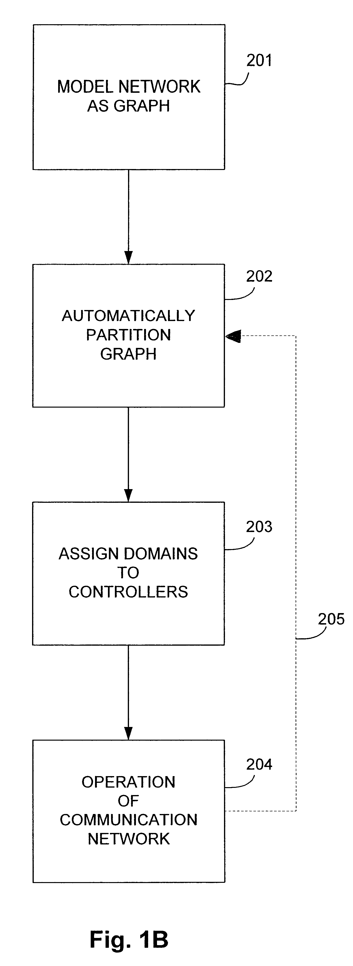
Method for automatic partitioning of node-weighted, edge-constrained graphs
a graph and edge constraint technology, applied in the direction of instruments, symbolic schematics, cad techniques, etc., can solve the problems of no known efficient method of solving this class of problems, inefficient method of solving large problems, and inability to solve large problems at the same time. the effect of reducing the number of problems
- Summary
- Abstract
- Description
- Claims
- Application Information
AI Technical Summary
Problems solved by technology
Method used
Image

Examples
example 1
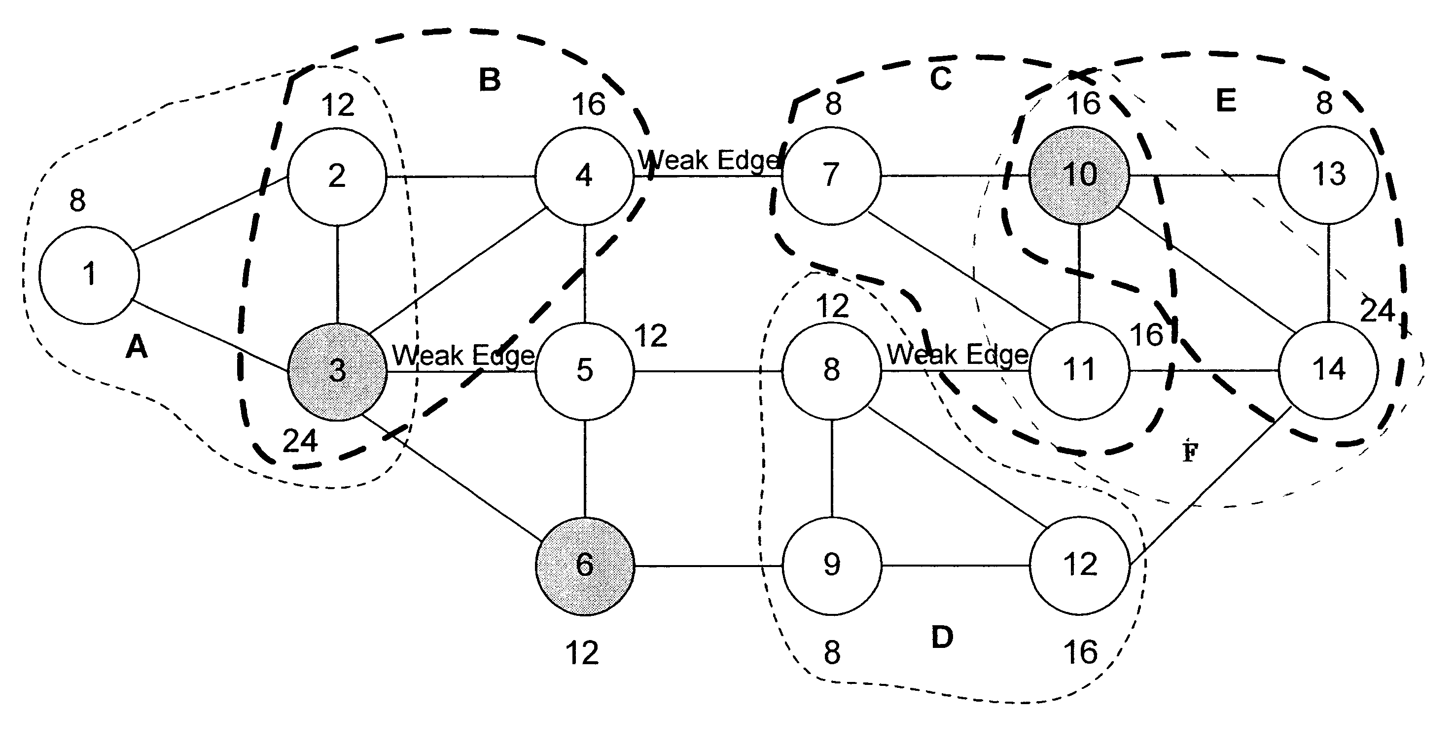
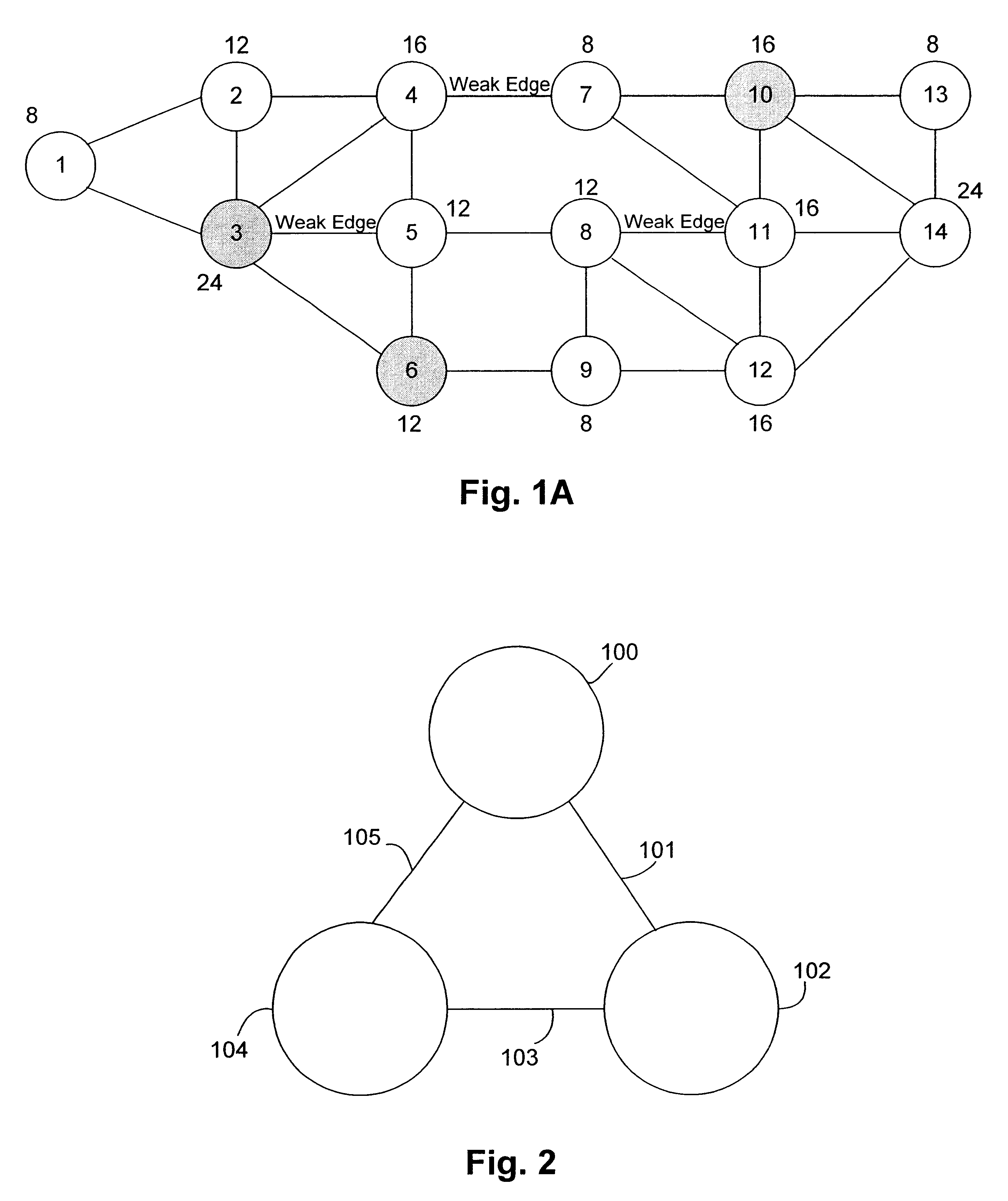
This example illustrates how the invention partitions the graph of FIG. 1A. FIG. 5A shows the graph of FIG. 1 including anchor nodes 3, 6 and 10. First, the weight range of the domains is determined (step 11 of FIG. 3A). The total weight of the graph is 192, and the theoretical average weight is 64 (i.e., 192 / 3). Since the minimum weight in the graph is 8, the range is (64-8, 64+8)=[56, 72]. The supernodes then are identified (step 13). These are denoted by dashed lines and labeled A, B, . . . , F in FIG. 5B. That is, the supernode list is {A, B, C, D, E, F}. Next, the uncovered nodes are identified and the uncovered node list is formed (step 15). This list is {5, 6}. Here, an anchor node (node 6) is an uncovered node. Since not more than half of the nodes are uncovered (step 16), the cluster formation phase is then commenced (step 17). Starting with anchor node 3, supernode A (containing nodes 1, 2 and 3) is chosen as the starting supernode and a member of a cluster. Supernode B ha...
example 2
In the example of FIGS. 6A-6C, a method for partitioning a different graph around anchor nodes is shown. There are three anchor nodes, 1, 6, and 11. These are shaded in FIG. 6A. In step 13, nine supernodes, labeled A through I in FIG. 6B, are identified, all of which form a single cluster, since each supernode has at least two nodes in common with an adjacent supernode.
Since there are three anchor nodes, 1, 6 and 11, clusters are partitioned around the anchor nodes (step 17). Supernode A is assigned to anchor node 1. This is because supernode A has no other nodes adjacent to an anchor node. Supernode E (or D, both meet the requirement) is assigned to anchor node 6, because supernode E (or D) has no other nodes adjacent to another anchor node. Supernode I is assigned to anchor node 11, because supernode I has only one other node adjacent to another anchor node (node 8 being adjacent to anchor node 6).
No other supernodes may be assigned to anchor node 1 in a next round, since no other...
example 3
This is a modification of Example 2. As shown in FIGS. 7A-7C, there are 11 weighted nodes all having the same weight, 8 for example, and two anchor nodes, nodes 5 and 9 (FIG. 7A). First, the domain weight range is determined (step 11). The total weight is 88 (8.times.11), and the average weight is 44 (88.div.2). Therefore, with a tolerance of .+-.8, the weight range is (44-8, 44+8)=[36, 52]. Nine supernodes are identified (step 13), labeled A through I in FIG. 7B, which form one cluster. Since there are no uncovered nodes (step 15), the cluster is partitioned into two clusters (one for each of anchor nodes 5 and 9).
Anchor node 5 forms the cluster made up of supernodes B, C, D and E, having a weight of 48 (step 17, 19). Anchor node 9 forms the cluster made up of supernodes F, G and H, having a weight of 40 (steps 17, 19). The unincluded supernode list is {supernode A, supernode I}. Since nodes 6 and 7 are contained in both clusters (step 31) and the weight of the cluster formed by an...
PUM
 Abstract
Description
Claims
Application Information