Wrist wallet with hook-to-mesh-fabric attaching means

a wrist wallet and fabric attachment technology, applied in the field of packaging and article containers, can solve the problems of not being able to allow cards to be placed in a manner of benefit to the wearer, and prior wrist wallets can be multi-layered or bulky

Inactive Publication Date: 2002-09-03
RITTMANN JEAN V
View PDF25 Cites 96 Cited by
  • Summary
  • Abstract
  • Description
  • Claims
  • Application Information

AI Technical Summary

Problems solved by technology

Prior wrist wallets can be multi-layered or bulky, and often must be taken off to access contents,

Method used


Image

  • Wrist wallet with hook-to-mesh-fabric attaching means
  • Wrist wallet with hook-to-mesh-fabric attaching means
  • Wrist wallet with hook-to-mesh-fabric attaching means

Examples


Embodiment Construction

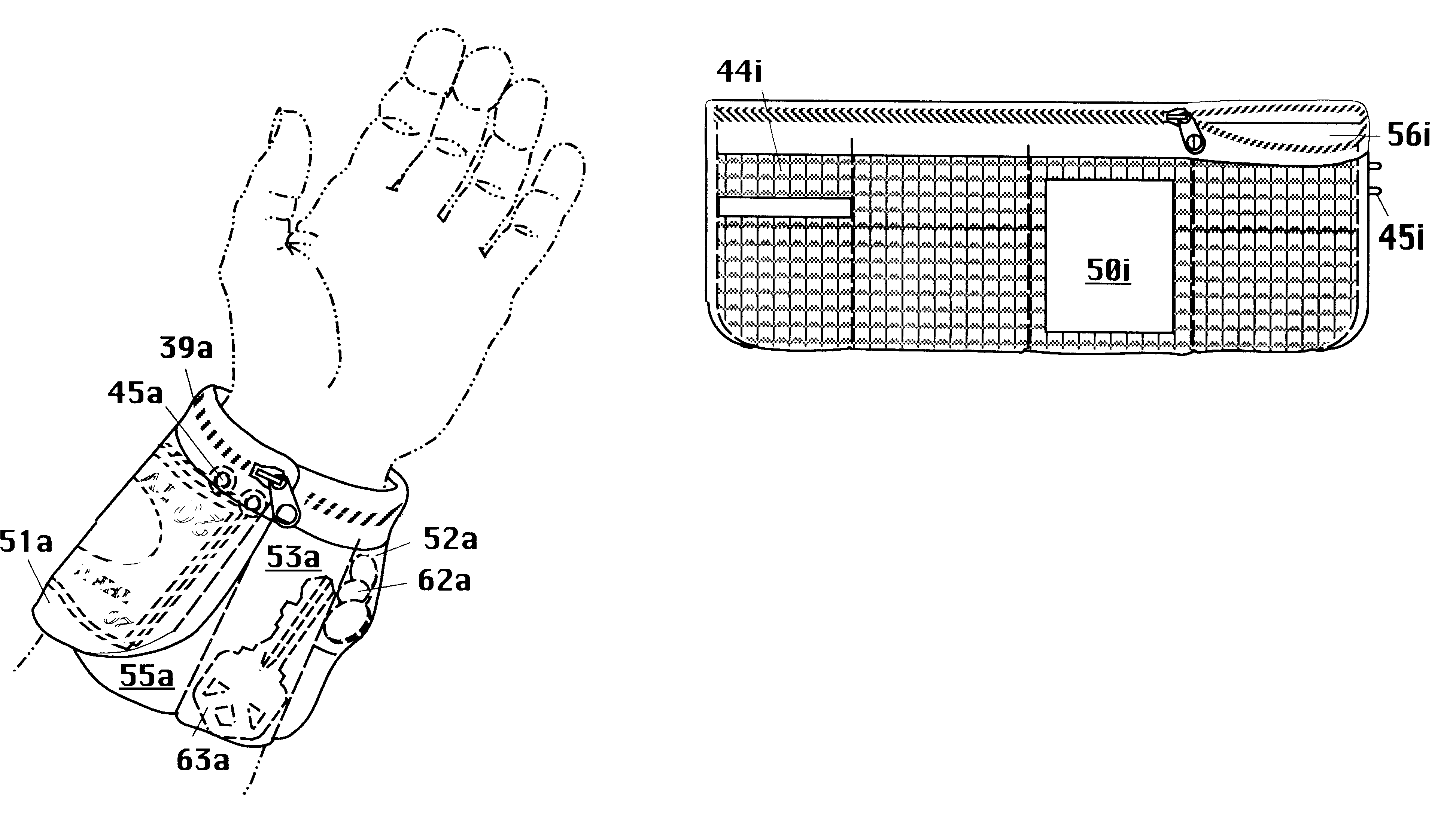
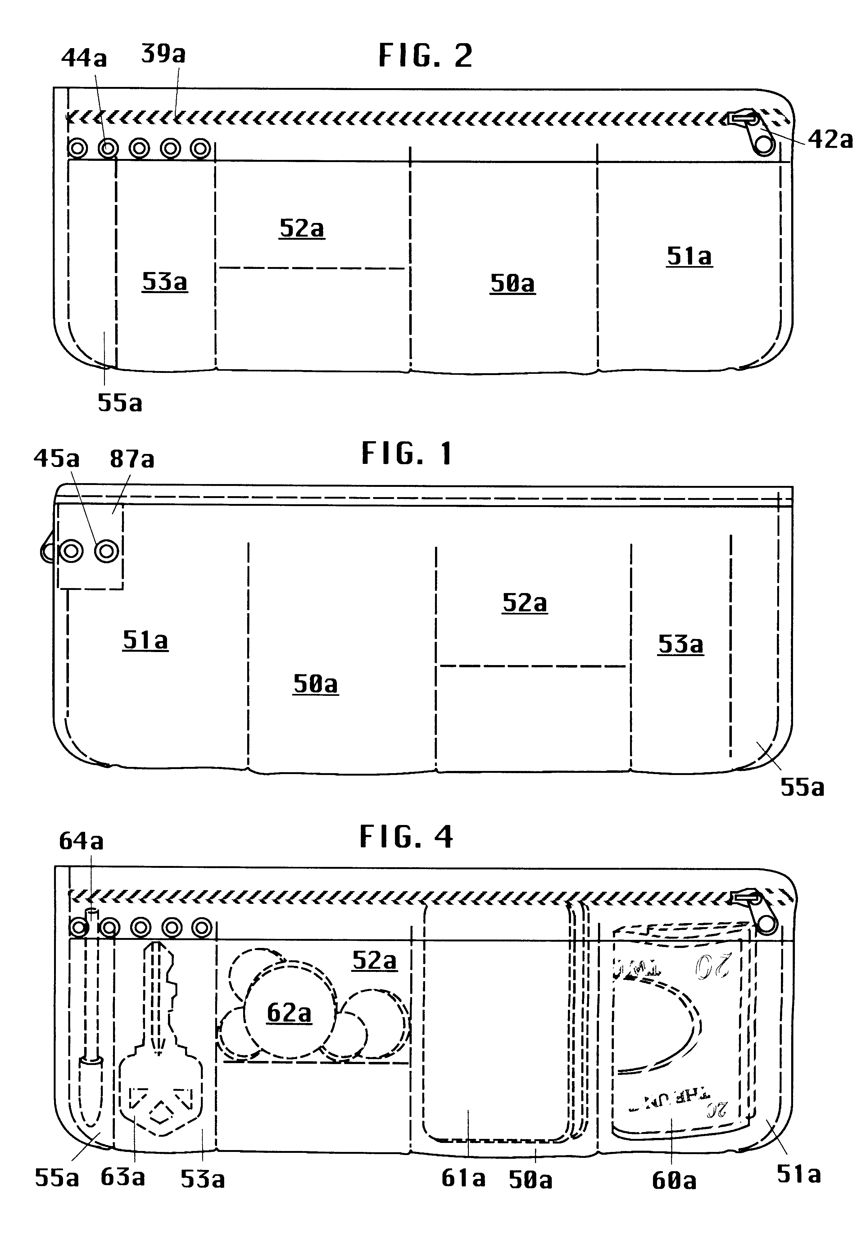
FIG. 2 shows a wallet embodiment, layed flat, front view. The wallet has lateral width and vertical height. Its width is of a size and shape to encircle a wearer's wrist. The height is of a size and shape to extend a parallel length to a wearer's forearm. Stitching on this and other embodiments is shown as long dashed lines. Wrist-encircling attaching means are side A snap sockets 45a snapped to side B snap studs 44a (attached to fabric rear section). Snaps attached to the strong zipper backing deters fabric tearing when snaps are pulled apart. A horizontally elongated zipper is the pocket sealing means. Prior art zipper teeth 39a position high on the pockets so items can be pulled out easily without lifting the top half of the pocket off the card's short edge. Noted are first, second, third, fourth, & fifth pockets 50a, 51a, 52a, 53a, and 55a respectively; and prior art zipper pull 42a.

FIG. 1 shows the embodiment of FIG. 2, rear view. Backing material 87a, when applied, keeps snap ...


PUM


Abstract

The invention is a wrist wallet, substantially made of mesh fabric, having laterally positioned first pocket (50a), second pocket, and third pocket. A lining is inside the third pocket. All pockets have a single laterally elongated sealing element at the top of the wallet in the form of a zipper having teeth (39a). The wallet has an attaching means that secures the wallet circumferentially about a wearer's wrist. The attaching means is hooks and eyes, the eyes being mesh fabric.

Description

Not applicable.STATEMENT REG. FED. SPONSORED R. OR D.Not applicable.REFERENCE TO A MICROFICHE APPENDIXNot applicable.BACKGROUND OF INVENTIONThis invention relates to Package and Article containers, carried by an animate bearer, held by receiver, with attaching means extending circumferentially of limb.Prior wrist wallets can be multi-layered or bulky, and often must be taken off to access contents, or have multiple straps to attach.Plastic cards .apprxeq.8.5.times.5.4 cm (3.4".times.2.1"), like driver's licenses, credit cards, insurance cards, etc. are carried by most adults in the U.S, and often require more access than cash. Many wrist wallets are not sized to contain such cards, let alone make them easy to access. Most wallets are designed for flexible dollar bills, and small items like coins, and keys; not rigid plastic cards. None allow cards to position in a manner of benefit to the wearer.Prior art U.S. Pat. No. 5,341,972. by R. Benton Jacks, granted Aug. 30, 1994, entitled W...

Claims


Application Information

Patent Timeline
IPC IPC(8): A45C1/00A45C1/04
CPCA45C1/04A45F2005/008
Inventor RITTMANN, JEAN V.
Owner RITTMANN JEAN V
Why Eureka
Try Eureka