Custom ankle brace system

a brace system and ankle technology, applied in the field of custom ankle brace systems, can solve the problems of limiting unaided mobility, awkward appearance and uncomfortable fit, and shoes costing at least double what would ordinarily be paid

Inactive Publication Date: 2002-09-03
ARIZONA AFO INC
View PDF3 Cites 23 Cited by
  • Summary
  • Abstract
  • Description
  • Claims
  • Application Information

AI Technical Summary

Benefits of technology

Moreover, this invention provides such an ankle brace system further comprising the steps of: making a positive cast from such negative cast in such manner that such markings are information-transferable to an outside surface of such positive cast; whereby such markings remain on such outside surface of such positive cast; and using such marking information, modifying such positive cast in such manner as to make such positive cast build-up for use in making such ankle brace for such patient. It also provides such an ankle brace system wherein such step of modifying such positive cast comprises the steps of: setting nails in such positive cast, the location and geometry of such nails being structured and arranged so that nailheads of such nails conform to such positive cast build-up; applying additional positive cast material to make such positive cast build-up; and smoothening such positive cast build-up.
Yet moreover, in accordance with a preferred embodiment thereof, this invention provides an ankle brace system for making, using a positive cast of the foot and lower leg of a patient, an ankle brace, for providing orthotic assistance to an ankle area of a patient, wherein such ankle area includes at least one abnormal protrusion enhancing disability for normal walking, and adapted to be worn inside a shoe, comprising the steps of: making a build-up of such positive cast in the area of such protrusion, sufficient to provide for patient comfort without loss of support; using such positive cast, making a support brace pattern having a single vertical seam on the heel side; making material layers to fit such support brace pattern; and making a stiffener element for use within such material layers in making such ankle brace for such patient; wherein such stiffener element is conformable to such positive cast when heated and comprises a partial sole portion and a leg back portion fixed at about a right angle from such partial sole portion. It also provides such an ankle brace system wherein making of such stiffener element comprises the steps of: providing, in a form large enough to enshroud such positive cast, a sheet of polymeric material shapable by vacuum forming when heated; heating such sheet until readily shapable; placing a talcum-powdered nylon material completely over such positive cast in such manner as to prevent such sheet from sticking to such positive cast; fully enshrouding such positive cast with such sheet by an air-tight envelopment but for an opening connected to a vacuum source; through such opening, using such vacuum source, creating a negative air pressure within such sheet sufficient to cause such sheet to conform to the shape of such positive cast; maintaining such negative air pressure until such sheet cools sufficiently to stiffen to such shape of such positive cast, thereby providing a shaped element; removing such shaped element from such positive cast; and trimming such shaped element in such manner as to provide such stiffener element.

Problems solved by technology

Typically, individuals suffer from certain conditions of the feet which either greatly limit unaided mobility or require the use of aids such as walkers or canes in order for the individual to be mobile.
To compensate for the above stated conditions, a person so afflicted must either compensate for it by purchasing a shoe or shoes that can be many sizes larger than they would normally require, resulting in an awkward appearance and an uncomfortable fit.
One set must be purchased in order to get a shoe that fits the unaffected foot, and the larger matching set to get a shoe that fits the afflicted foot, resulting in a pair of shoes costing at least double what would ordinarily be paid.
Generally, the braces used for these types of ailments are large, thick, and cumbersome, which make them inconvenient to use, awkward in appearance and awkward in fit, and often resulting in sores.

Method used


Image

  • Custom ankle brace system
  • Custom ankle brace system
  • Custom ankle brace system

Examples


Embodiment Construction

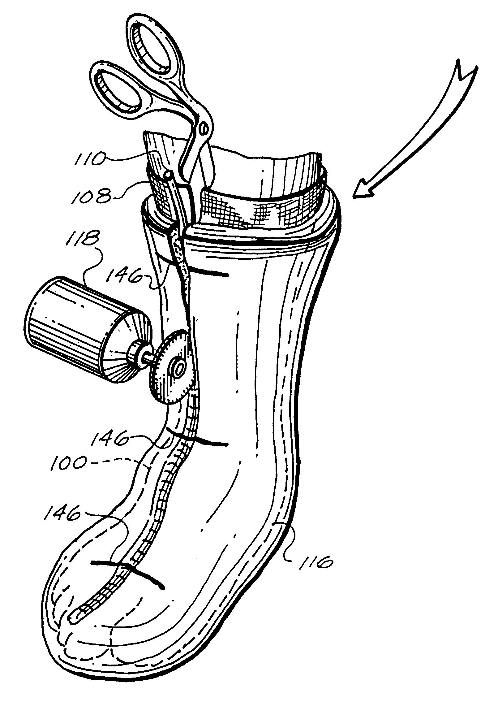
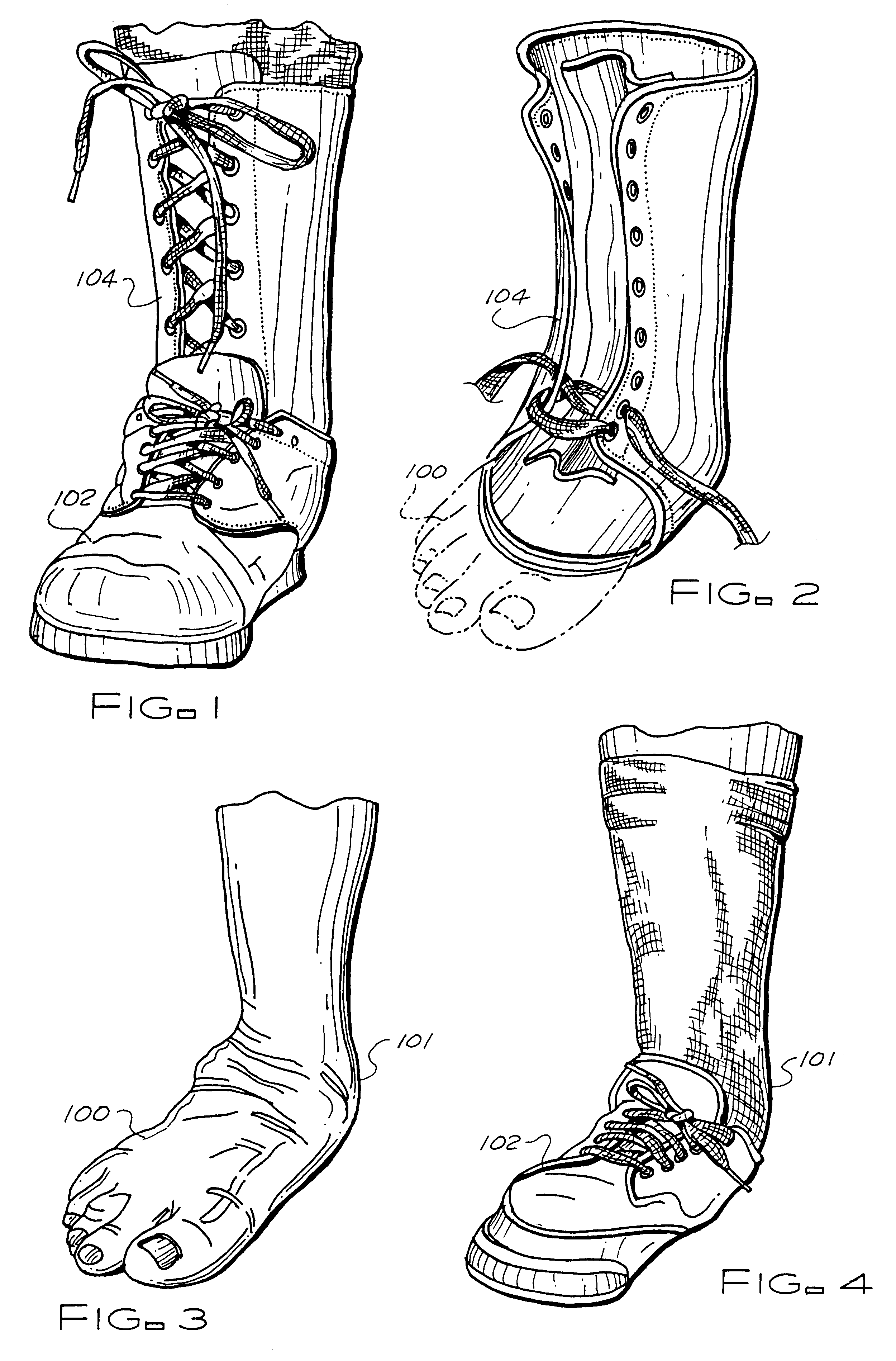
FIG. 1 illustrates the custom ankle brace 104 of this invention according to a preferred embodiment thereof. Shown is a shoe 102 worn over the custom ankle brace 104, both holding the patient's foot 100. Typically, the custom ankle brace 104 allows for the patient to wear a shoe size 1 / 2 size larger than normal. This is a marked improvement for patients with the type of ailments that the present invention was designed for and it's intended use. Each custom ankle brace 104 is custom manufactured to the specific needs and physical properties of the individual patient's foot 100. FIG. 2 illustrates just the custom ankle brace 104. FIG. 3 represents one possible combination of foot ailments suggesting the use of the custom ankle brace 104. In FIG. 3, a patient's foot 100 is shown with severe pronation and a sensitive bony prominences 101 that would make it difficult for the patient to wear a shoe 102, as illustrated in FIG. 4, and difficult to walk without the use of a brace. Often thes...


PUM


Abstract

A custom ankle brace which is made to compensate for debilitating conditions of an individual patient's ankle area. The brace is custom made by creating a negative cast of the patient's foot / ankle / lower-leg; and then prescribed markings are included on the negative cast by the castmaker to indicate the desired geometry of support. The markings are transferable to a positive cast to inform the bracemaker. The custom brace has inner and outer material layers with a stiffening element within, all fitted to the shape of a built-up positive cast, the stiffening element having a unitary horizontal partial sole portion and vertical back-and-sides-of-leg portion. The stiffening element, made from a thin polymeric sheet, is vacuum and heat fitted to the built-up-positive cast.

Description

1. Field of the InventionThis invention relates to providing a custom ankle brace system. More particularly, this invention concerns such a system for being of help to patients whose ankle conditions are of certain types and no longer permit them to walk properly without some sort of custom orthotic.2. Description of the Prior ArtTypically, individuals suffer from certain conditions of the feet which either greatly limit unaided mobility or require the use of aids such as walkers or canes in order for the individual to be mobile. Conditions which may cause this debilitating condition include tibialis tendinitis or rupture, degenerate joint disease, talocalcaneal varus or valgus, severe pronation, and / or trauma to ankle, subtalar, or midtarsal. To treat these conditions necessarily requires a stabilizing-type apparatus in order to stabilize the ankle area, talocalcaneal, midtarsal, and subtalar joints so that medial and lateral stability of the foot is achieved with the result that t...

Claims


Application Information

Patent Timeline
Patent Type & Authority Patents(United States)
IPC IPC(8): A61F5/01
CPCA61F5/0111
Inventor CASTRO, ERNESTO G.
Owner ARIZONA AFO INC
Why Eureka
Try Eureka