Optical sheet, and backlight unit and display having plural microlenses on lens sheet with respective light transmission parts and pairs of reflection layers sandwiching the light transmission parts

a backlight unit and lens technology, applied in the field of display devices, can solve the problems of unsuitable practical use, increase in power consumption of light sources, etc., and achieve the effects of bright image display, and improving the utilization efficiency of light 6 from the light sour

Inactive Publication Date: 2008-09-23
TOPPAN PRINTING CO LTD
View PDF6 Cites 9 Cited by
  • Summary
  • Abstract
  • Description
  • Claims
  • Application Information

AI Technical Summary

Benefits of technology

[0013]However, in a case of such an optical sheet B, the exiting light enters into a liquid crystal panel D as parallel rays. Therefore, utilization efficiency of the light 6 from the light source can be improved, and the distribution of the exiting light can be controlled, thereby a bright image display can be realized. On the other hand, this light goes in a direction which is perpendicular to a surface of the optical sheet B. Therefore, a bright image display can not be observed from an oblique direction. Therefore, there is a problem in that the view angle is limited.
[0014]Then, the object of the present invention is to provide an optical sheet, and a backlight unit and a display apparatus using the optical sheet. In the present invention, utilization efficiency of the light 6 from the light source can be improved, and the distribution of the exiting light can be controlled. Further, the view angle of the display is broadened so that a bright image display can be observed from an oblique direction.
[0020]A straight line between an inside corner of a light reflection film which is one of a pair of light reflection films sandwiching a light transmission part and an outside corner of the other light reflection film is on the inside of the limit normal line. Therefore, a light refracted by the side surface of the projection is refracted in the direction closer to a lens sheet side wherein the amount of light refracted in the direction closer to a lens sheet side can be sufficiently provided, thereby the view angle of the display image can be broadened.
[0024]Next, the side surface of the projection can be planar or curved. The distribution of the exiting light can be controlled by changing the shape of the side surface of this projection. In a case of a planar side surface, an amount of light which exits in an oblique direction towards a (flat) surface of the optical sheet is increased, thereby the view angle can be improved. In addition, for example, in a case of a curved side surface like a convex, an amount of a light which exits in a direction which is perpendicular to a surface of the optical sheet is increased, thereby a displayed image observed from a front side of the display can be brightened.
[0029]Next, in the invention of claim 7, an optical sheet and a light scattering layer are unified so that the handling of them becomes easy. That is, the invention of claim 8 is the invention according to claim 6, wherein a light scattering layer adheres to the light reflection layer.

Problems solved by technology

High luminance can be realized by increasing the number of light sources such as a cold-cathode tube, however the increasing number of light sources contributes to the increase of power consumption.
Therefore, it is not suitable for practical use.

Method used


Image

  • Optical sheet, and backlight unit and display having plural microlenses on lens sheet with respective light transmission parts and pairs of reflection layers sandwiching the light transmission parts
  • Optical sheet, and backlight unit and display having plural microlenses on lens sheet with respective light transmission parts and pairs of reflection layers sandwiching the light transmission parts
  • Optical sheet, and backlight unit and display having plural microlenses on lens sheet with respective light transmission parts and pairs of reflection layers sandwiching the light transmission parts

Examples


Embodiment Construction

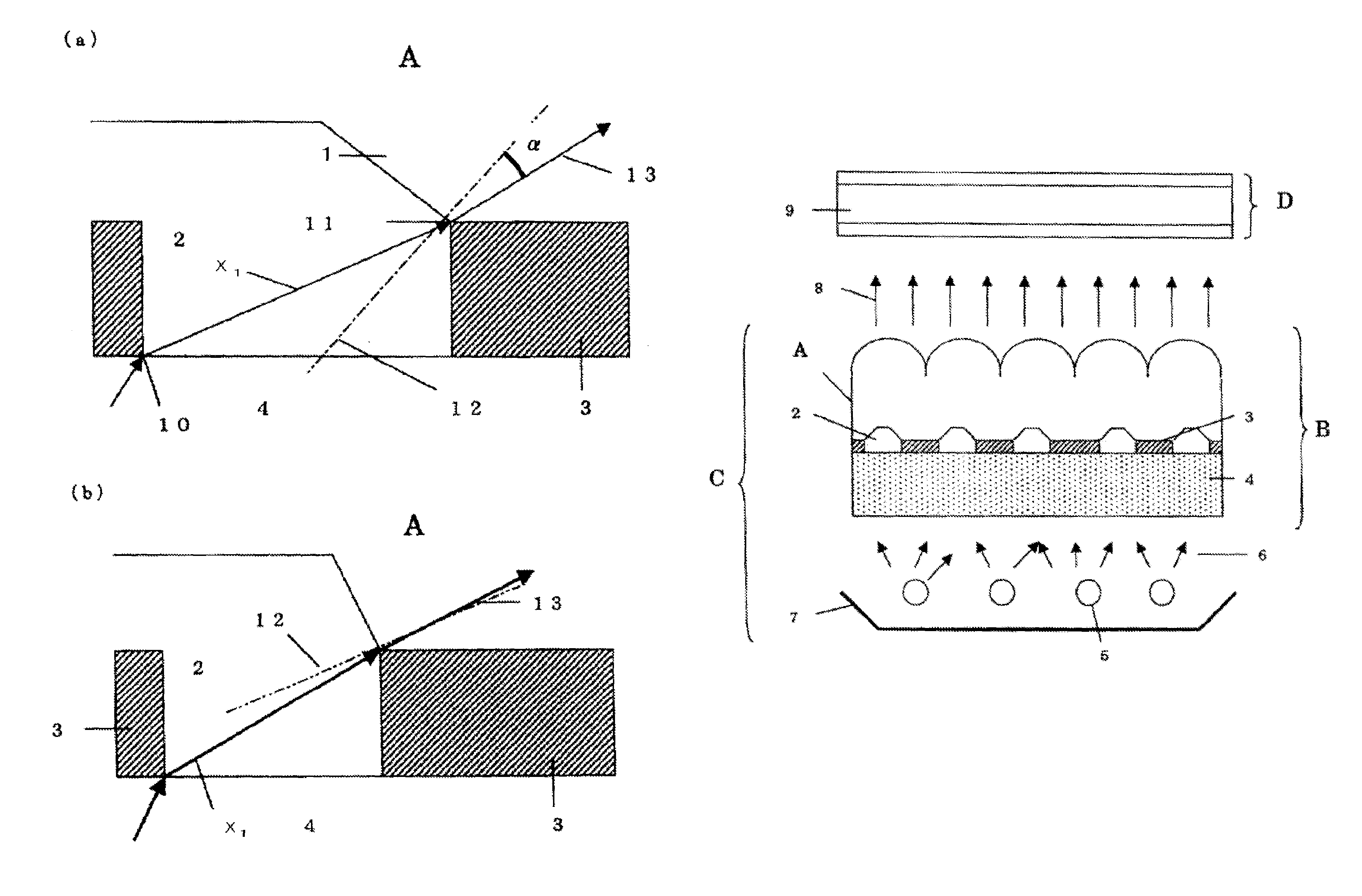
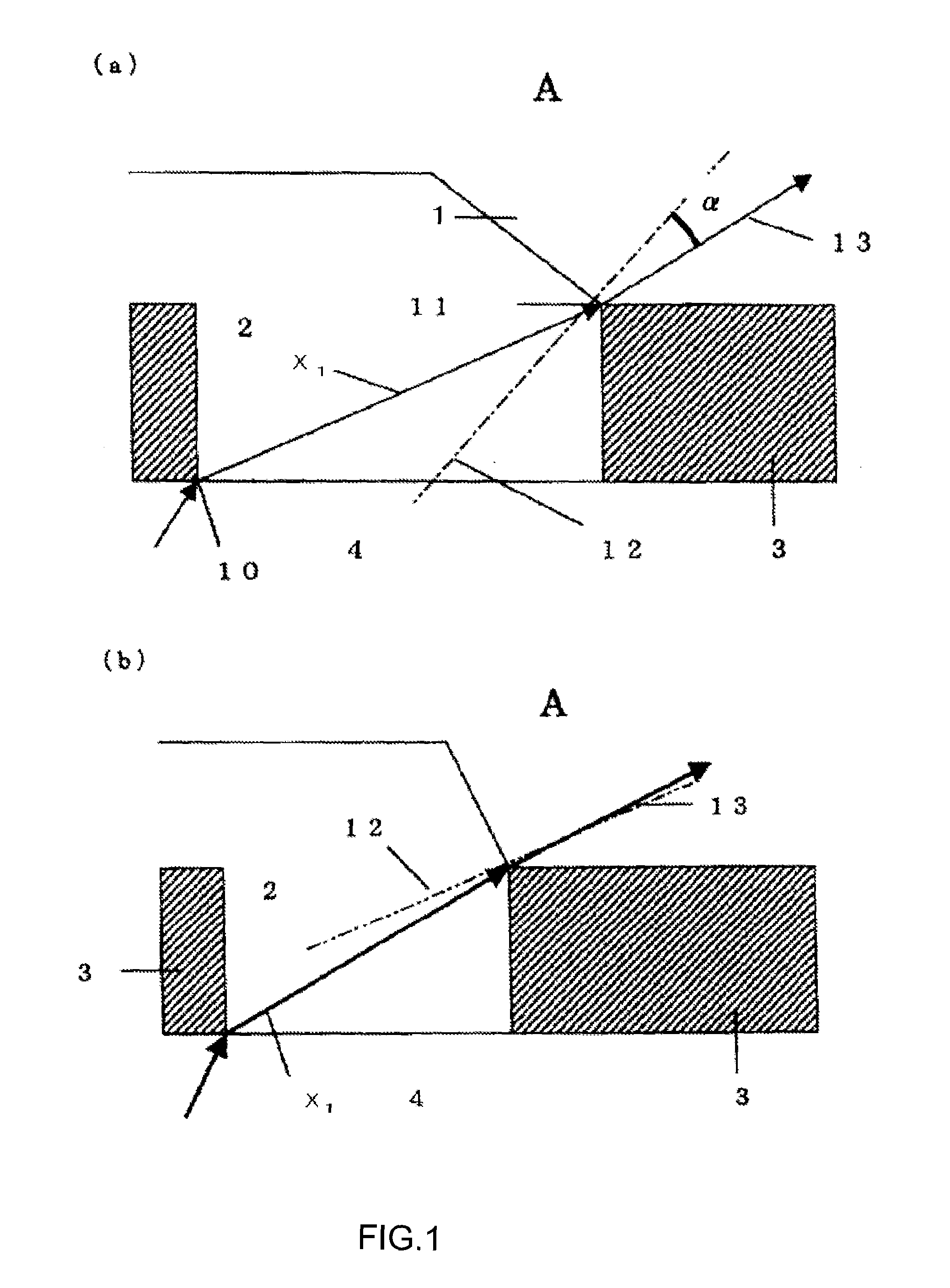
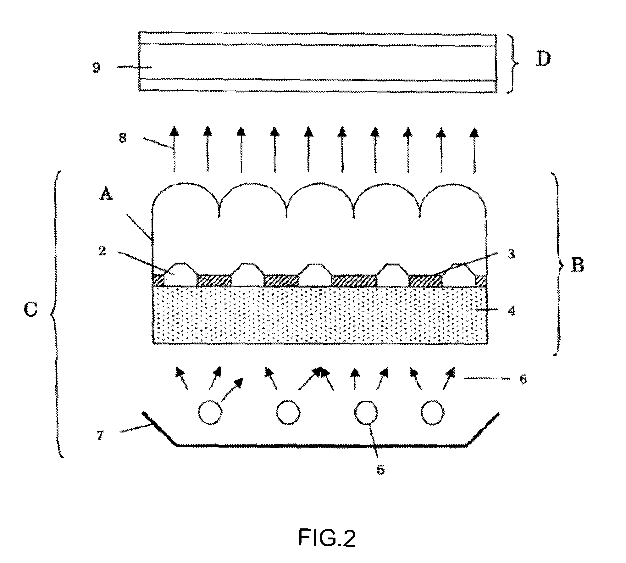
[0045]An optical sheet of the present invention is arranged in a back side of a display panel, wherein the light from the optical sheet enters into this display panel. This optical sheet is used as a part of a backlight unit. FIG. 2 shows a display apparatus, wherein a backlight unit is arranged in a back side of a display panel.

[0046]The display panel has a plurality of sectioned pixels, wherein a screen is displayed by the contrast between a light transmission part and a shaded part where the light transmission or shading is controlled for these pixel units.

[0047]The backlight unit has a light source, a light reflection plate arranged in back side of the light source, and an optical sheet arranged between the light source and the display panel. The light reflection plate is used for improving the utilization efficiency of a light from a light source by reflecting the light from the light source in the direction of the optical sheet. In addition, the optical sheet makes the luminan...


PUM

PropertyMeasurementUnit
heightaaaaaaaaaa
heightaaaaaaaaaa
heightaaaaaaaaaa

Abstract

One embodiment of the present invention is an optical sheet including a lens sheet having a plurality of microlenses arranged on a front surface thereof and a plurality of projections located at a back side thereof, a projection being located between light transmission parts, and a part corresponding to the microlens being the light transmission part; and a plurality of light reflection layers provided on top of the plurality of projections. A light refracted by the side surface of the projection exits in an oblique direction towards a plane of the optical sheet. Thereby, the view angle can be broadened.

Description

CROSS-REFERENCE TO RELATED APPLICATIONS[0001]This is a Continuation Application of PCT Application No. PCT / JP07 / 052132, filed Feb. 7, 2007, which is incorporated herein by reference in its entirety.[0002](Claims in this application were allowed on Oct. 16, 2007 by Japan Patent Office)BACKGROUND OF THE INVENTION[0003]1. Field of the Invention[0004]The present invention is related to a display apparatus where a light transmission and a light shading are controlled for every pixel to display an image, and a backlight unit and an optical sheet used for this display. An examples of such a display apparatus includes a liquid crystal display.[0005]2. Description of the Related Art[0006]A liquid crystal display apparatus using a transmission type liquid crystal panel has a backlight unit and a liquid crystal panel where pixels are arranged like dots. A character or an image can be displayed by controlling a light transmittance of each pixel. The following are types of backlight unit: the di...

Claims


Application Information

Patent Timeline
Patent Type & Authority Patents(United States)
IPC IPC(8): G02F1/1335
CPCG02B3/0031G02B3/005G02F1/133512G02F1/133606G02B5/005G02F2001/133607G02F1/133607
Inventor TAKAYAMA, HISASHI
Owner TOPPAN PRINTING CO LTD
Why Eureka
Try Eureka