Decoy apparatus with adjustable pitch rotor blade wing assembly

a technology of rotor blades and rotor blades, which is applied in the field of decoy apparatuses, can solve the problems of environmental damage to and limited effectiveness of decoys employing motorized systems for animation

Inactive Publication Date: 2002-09-17
PRICE FRED F
View PDF17 Cites 28 Cited by
  • Summary
  • Abstract
  • Description
  • Claims
  • Application Information

AI Technical Summary

Benefits of technology

In the preferred embodiment, each wing of the decoy apparatus includes two vertically aligned dorsally / ventrally-opposed rotor blade members proximally located relative to the wingless imitation body structure and weighted so as to allow the wings to rotatably rest with their ventral surface down facing downward. The vertically aligned, dorsally / ventrally-opposed propeller-shaped rotor blade members each have a pitch control means, which rotatably mounts each vertically-aligned, dorsally / ventrally-opposed propeller-shaped rotor blade member onto the respective wing. Each pitch control means allows for setting the pitch of the rotor blade member enabling each rotor blade member to be positioned in a preset orientation with respect to the wing to adjust for the desired collection of available kinetic wind energy to achieve the most efficient RPM rotational value of the wings and rotor blade members according to the field conditions or availability of kinetic wind energy where the waterfowl decoy apparatus is set-up for decoy attraction purposes.
Additionally, it is a further object of the present invention to simulate the myriad bodily movements of which waterfowl are capable, thereby adding to the effectiveness of the decoy apparatus. Accordingly the decoy apparatus is fixedly mounted on a swivel mounting system. The swivel mounting system allows the decoy apparatus to be selectively oriented in a triaxial fashion further allowing the user to randomly position the decoy apparatus. The decoy apparatus is mounted on a swivel head assembly, which allows for the selective triaxial orientation. A rod-like anchoring post supports the swivel head assembly. The rod-like anchoring post has a support end and an anchoring end opposite the support end. The support end rotatably attaches to the swivel head and the anchoring end has a pointed terminus for piercedly and fixedly anchoring the rod-like anchoring post to the ground.

Problems solved by technology

The use of these live so-called decoys, however, was outlawed in the United States in 1935, prompting hunters in the United States to find life-like substitutes.
Decoys employing motorized systems for animation, however, are both detrimental to the environment and have limited effectiveness.
Decoys employing motorized systems for animation are environmentally detrimental in that power sources are often discarded into the environment.
Further, decoys employing motorized systems for animation are limited in their effectiveness in that the visually apparent animation they exhibit tends to be static, mechanical and highly repetitive.
Additionally, motorized systems for animation often conflict with environmental conditions, namely wind conditions, and tend to wear more quickly due to oppositional forces impinging upon mechanically operative parts.
Wind-actuated systems for decoy animation rarely result in environmentally discarded material.
Moreover, wind-actuated systems for decoy animation harness wind energy operate in tune with wind conditions and wear more slowly as a result.
The shape of the rotatable wings is not visually imitative thus limiting decoy effectiveness.
Further, the rotatable wings are not integrally formed with the bird decoy body structure, which detracts from the decoy's visually imitative effect thus limiting decoy effectiveness.
Moreover, the rotatable wings are not readily viewable from extreme lateral viewpoints thus further handicapping decoy effectiveness.
This disclosure is not visually imitative in that it lacks the preferable integral wing to body configuration and seems awkward in practice.
While the vane blades approach a more life-like wing shape, the support structure simultaneously detracts from the lure's visually imitative effect thus limiting decoy effectiveness.
Further, the blade members do not produce a visually alternating signal viewable from extreme lateral viewpoints, thus further limiting decoy effectiveness.
None of the prior art discloses wind-driven rotatable wings that employ rotor blades for collecting and converting wind energy into rotational power to rotatably drive a shaft member integrally mounted with a decoy body structure.
Further, none of the prior art discloses rotatable wings readily viewable from extreme lateral positions.
Attempting to simulate these in an artificially animated decoy is difficult.
None of the prior art patents shows a mounting system that enables the user to selectively position the decoy in a triaxial manner.

Method used


Image

  • Decoy apparatus with adjustable pitch rotor blade wing assembly
  • Decoy apparatus with adjustable pitch rotor blade wing assembly
  • Decoy apparatus with adjustable pitch rotor blade wing assembly

Examples


Embodiment Construction

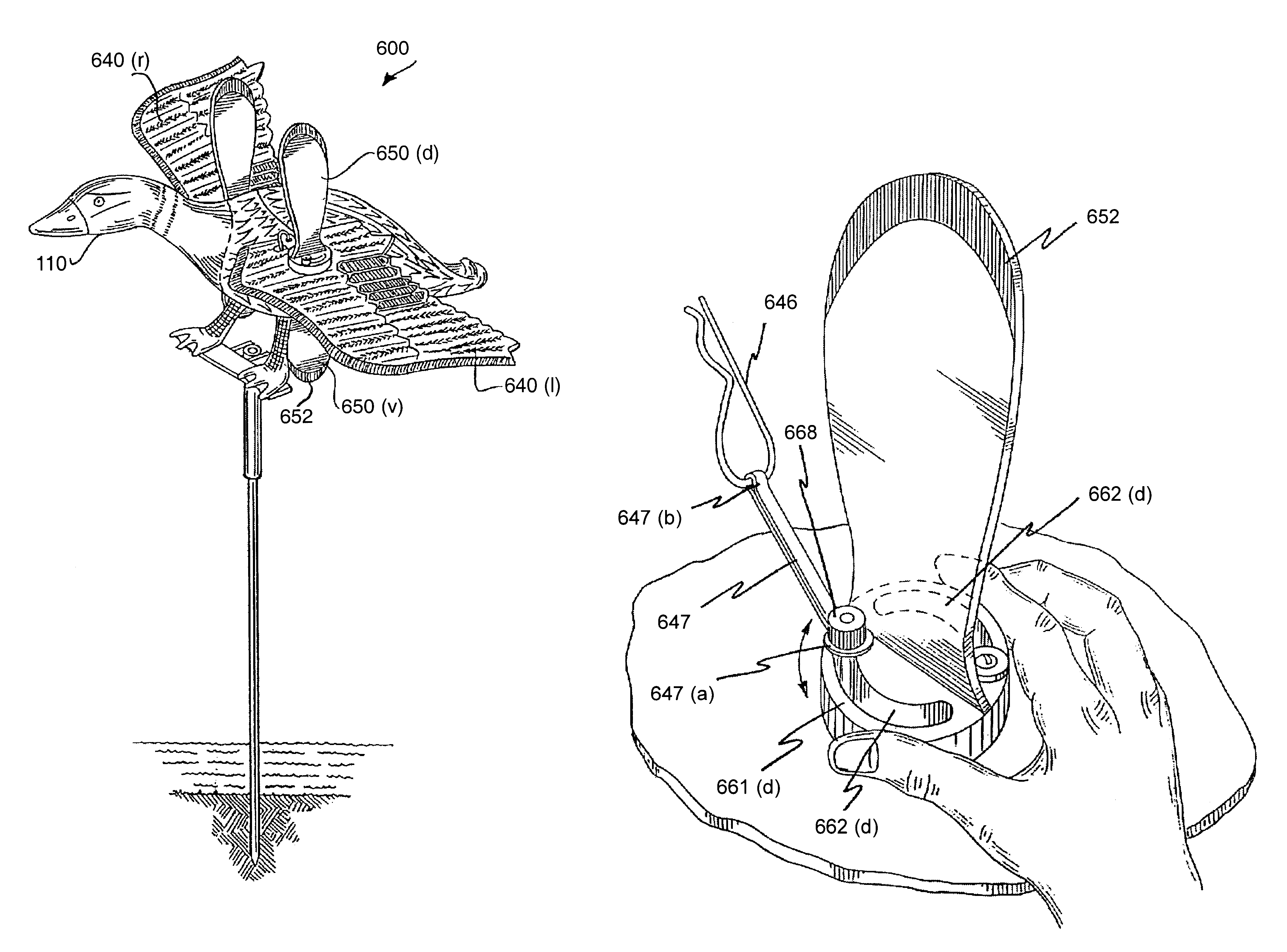
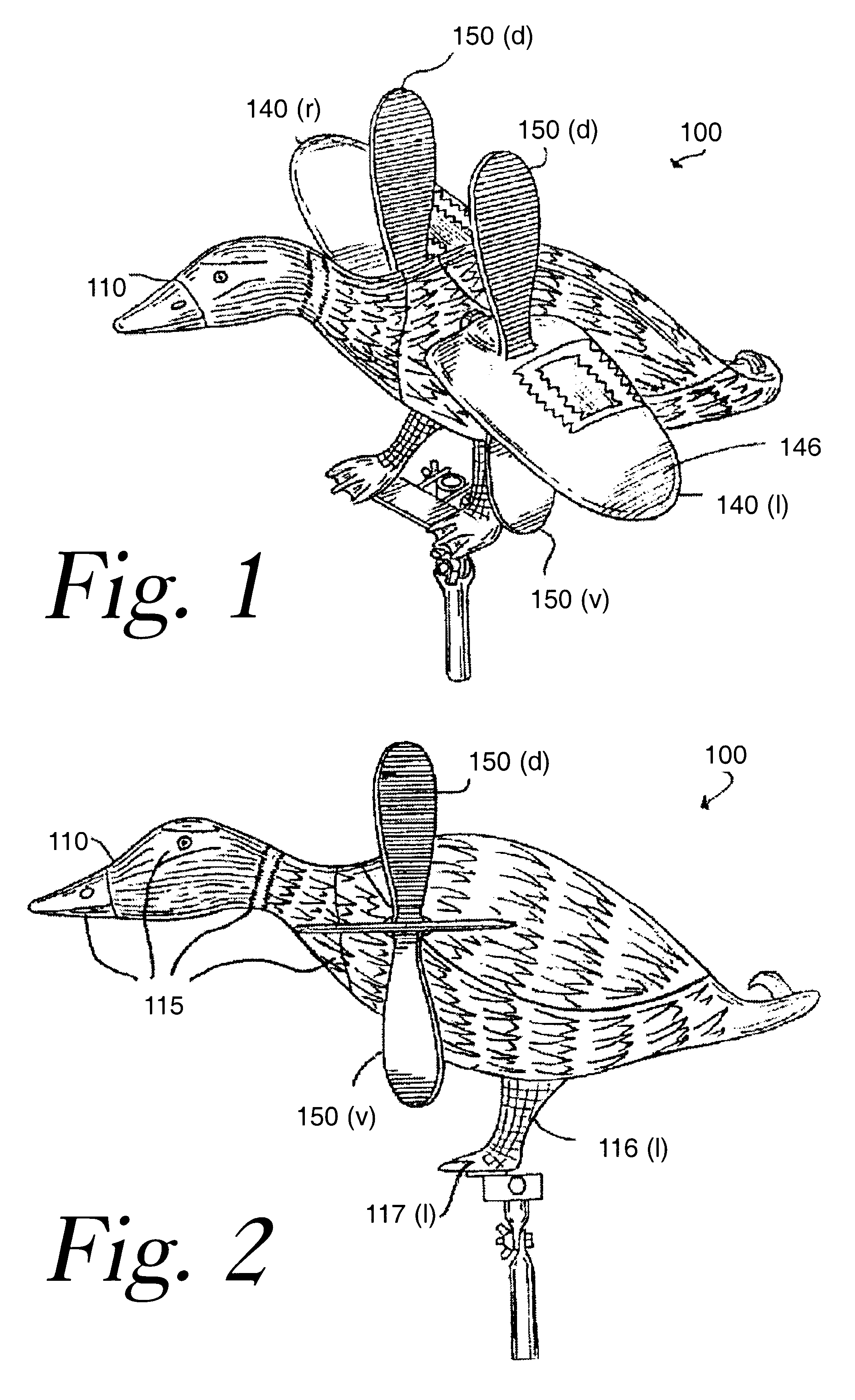
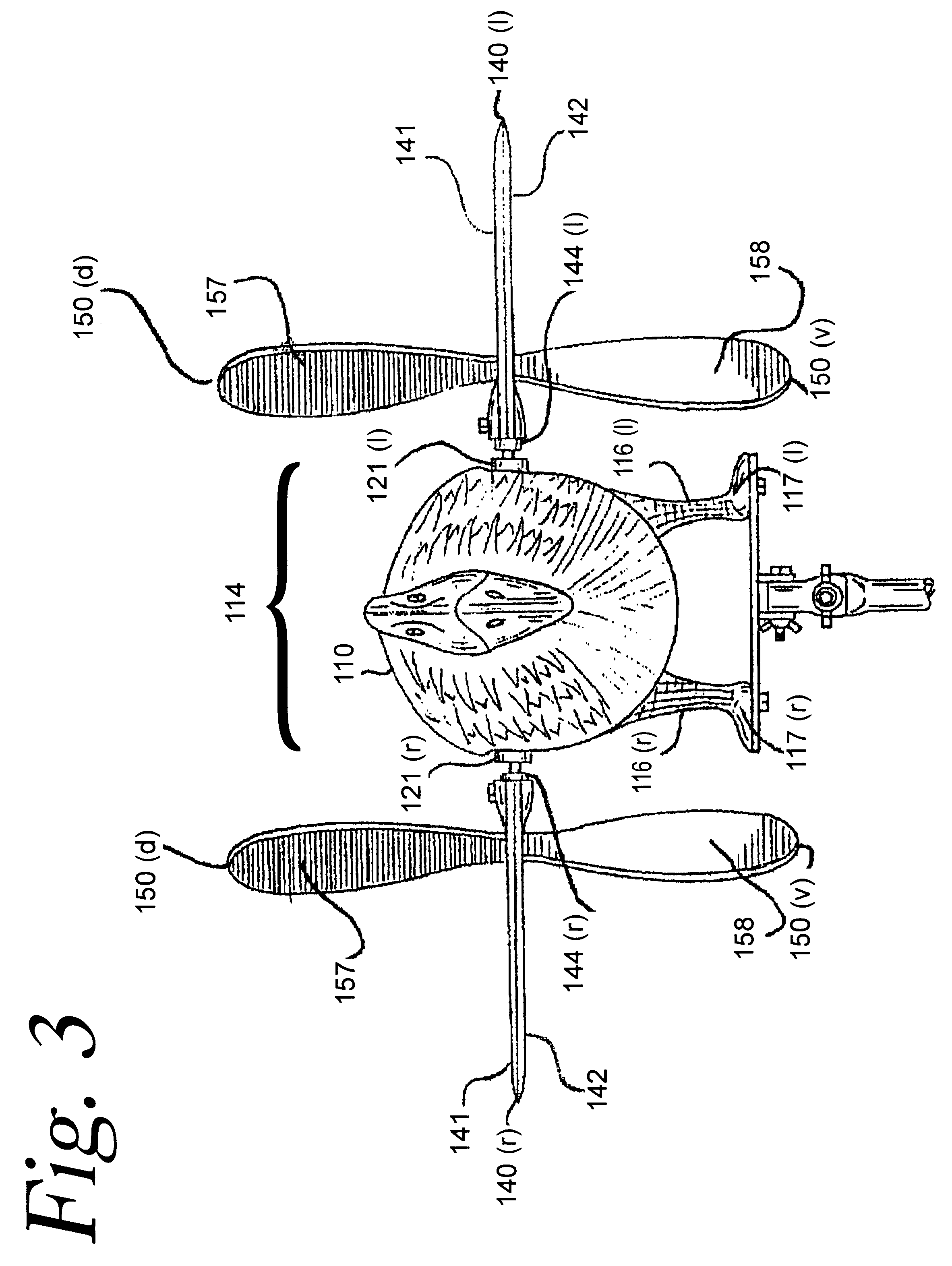
The preferred embodiment of the waterfowl decoy apparatus 600 is shown in FIG. 18. The preferred embodiment of waterfowl decoy apparatus 600 generally consists of wingless imitation waterfowl structure 110, shaft housing 620 as shown in FIG. 25, FIG. 25(a) and FIG. 25(b), bearing members 622(l) and 622(r) as shown in FIG. 24 and FIG. 25, a shaft member 630 as shown in FIG. 19, FIG. 24 and FIG. 25, a wing 640(l) and a wing 640(r) as shown in FIG. 19, dorsally-located rotor blade members 650(d) and ventrally-located rotor blade members 650(v) as shown in FIG. 22. The preferred embodiment is virtually identical to the alternative embodiments of waterfowl decoy apparatus 100, waterfowl decoy apparatus 200 and waterfowl decoy apparatus 300 save for its shaft housing 620, its bearing members 622(l) and 622(r), its shaft member 630, its wing 640(l) and wing 640(r), its dorsally-located rotor blade members 650(d), its ventrally-located rotor blade members 650(v), and an additional pitch con...


PUM


Abstract

The present invention discloses a decoy apparatus with wind-driven rotatable wings. The rotatable wings are mounted on a shaft member, which extends transversely through a bird-like body portion. Adjustable-pitch rotor blades are integrally mounted on the rotatable wings for collecting and converting kinetic wind energy to rotational power in the shaft member. When collected and converted to rotational power, wind energy causes the wings, the shaft member and the rotor blades to rotate in unison through 360 degrees about a horizontal axis of rotation extending through the shaft member. The wings and integrally mounted rotor blades co-rotate in a clockwise direction or in a counter-clockwise direction depending on the wind energy being directed against the rotor blade members. The adjustable pitch rotor blade members thus create wing movement in the wings and in the rotor blades for alluring game located vertically, laterally and longitudinally relative to the decoy apparatus.

Description

1. Field of the InventionThe present invention relates to a decoy apparatus, and, more particularly, to a decoy apparatus with rotatable wing assemblies for alluring birds within visual distance of the decoy apparatus regardless of their environmental location.2. Description of the Prior ArtDecoy art is ancient. Hunter societies on the American Continent have used decoys in their hunt for centuries. These ancient decoys were designed, in part, to bring game birds within close proximity to the hunters due to the relatively primitive weaponry of the day. Bird decoys estimated to be over a thousand years old and made of reeds and feathers have been discovered and preserved from these earlier times. Down through the centuries, hunters have continually endeavored to improve upon their decoys and the process of continual improvement persists to this day.Despite the trend to constantly improve upon that which has come before, it is well known in the art that waterfowl decoys, in particular...

Claims


Application Information

Patent Timeline
Patent Type & Authority Patents(United States)
IPC IPC(8): A01M31/00A01M31/06
CPCA01M31/06
Inventor PRICE, SR., FRED F.DESMIDT, JAMES J.
Owner PRICE FRED F
Why Eureka
Try Eureka