Double-loop catheter

a multipleloop catheter and catheter technology, applied in the direction of guide wires, medical devices, other medical devices, etc., can solve the problems of catheter not functioning properly, catheter still subject to dislodging by patient movement, and inability to dislodge the catheter in an unacceptable situation

Inactive Publication Date: 2002-09-24
MODY MALAY K DR
View PDF23 Cites 52 Cited by
  • Summary
  • Abstract
  • Description
  • Claims
  • Application Information

AI Technical Summary

Benefits of technology

It is still a further object of the present invention to provide a catheter, as above, wherein the loop hole, the transition holes, and the end hole are aligned with one another when the loops are fully formed. The hub provides a pivotable locking dev

Problems solved by technology

Although forming of a single loop at the end of the catheter has been shown effective in use, it is still subject to dislodging by movement of the patient, as the patient gets in and out of bed or as the patient rolls over while sleeping.
Of cours

Method used


Image

  • Double-loop catheter
  • Double-loop catheter
  • Double-loop catheter

Examples


Embodiment Construction

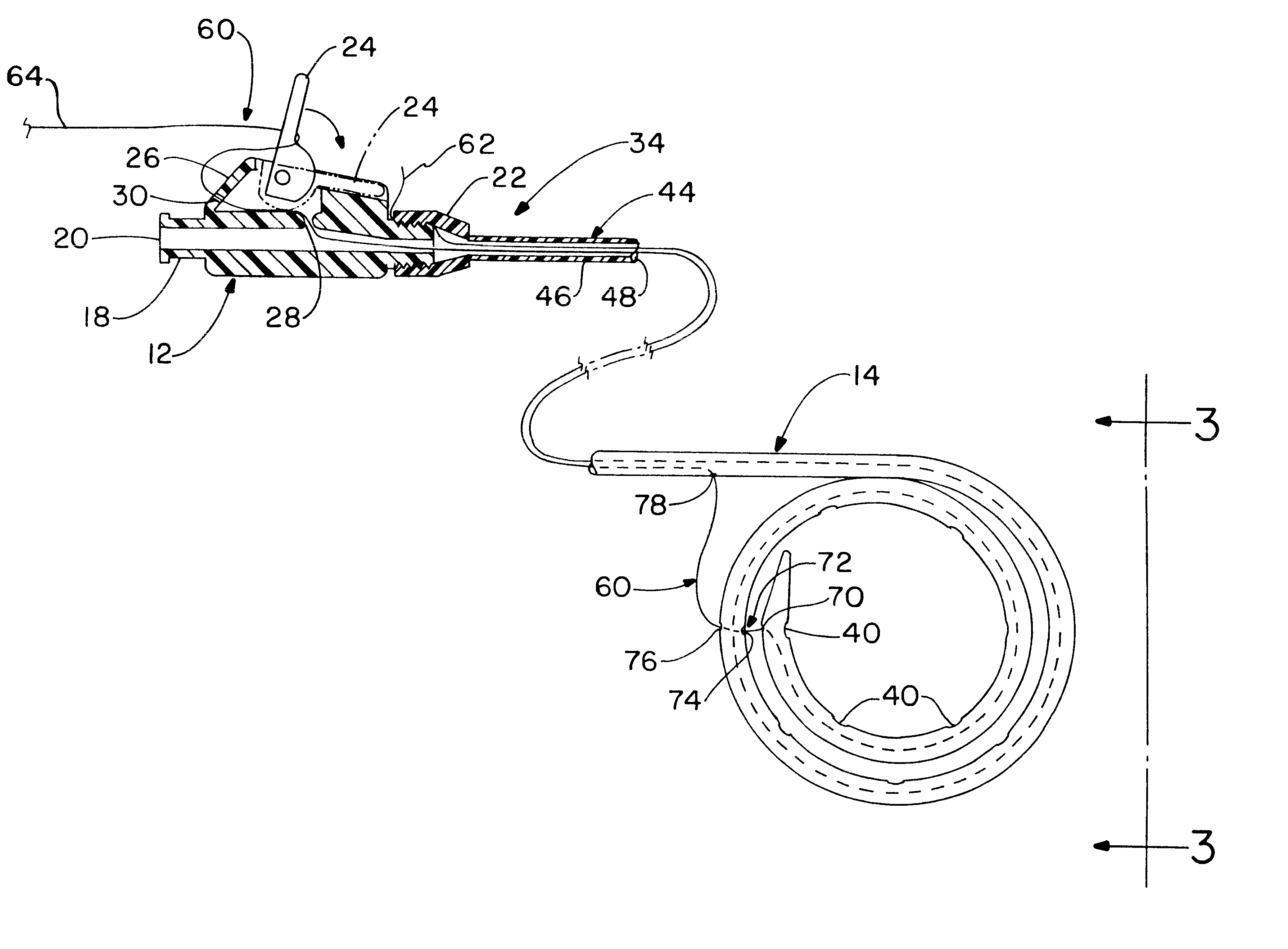
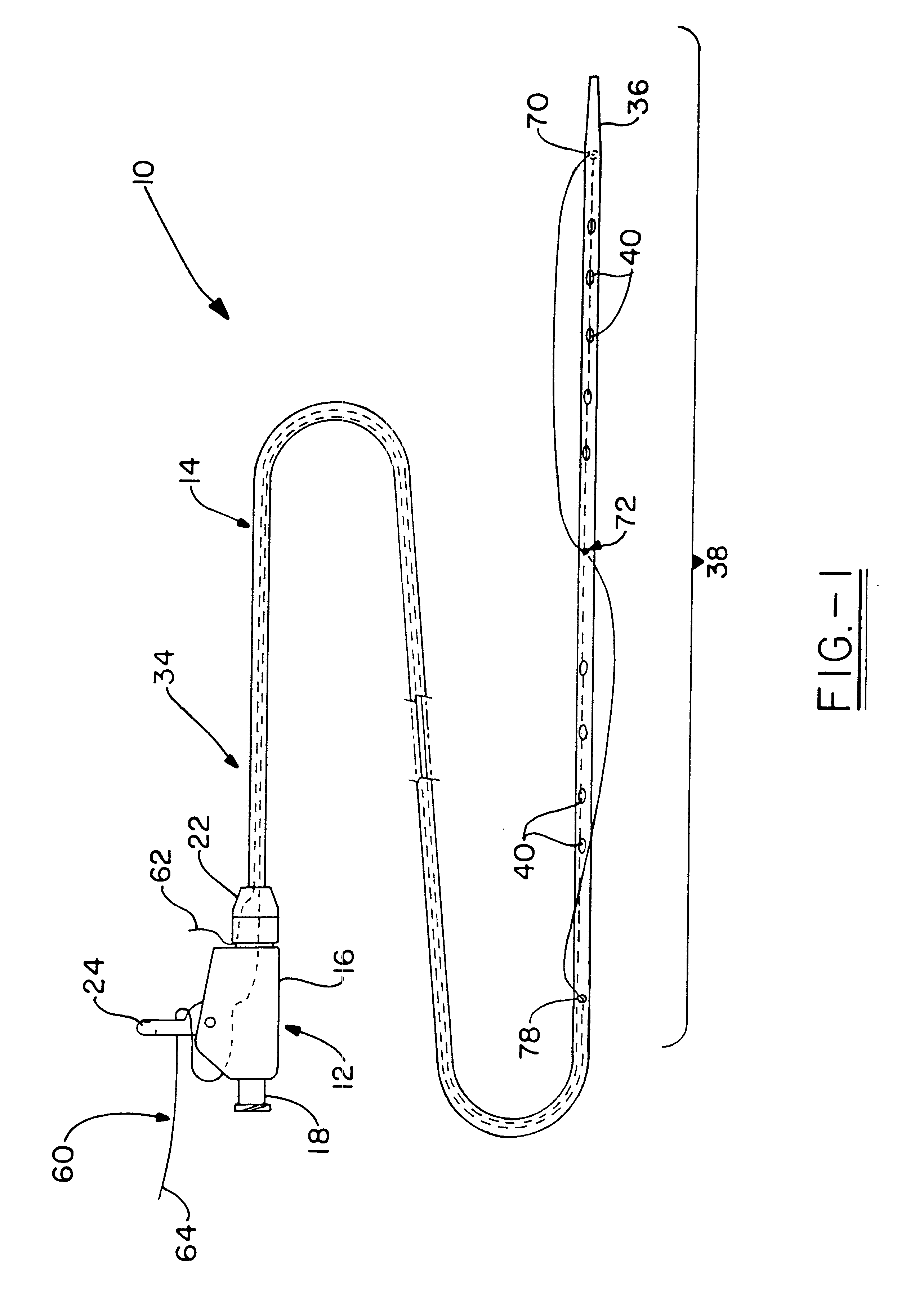
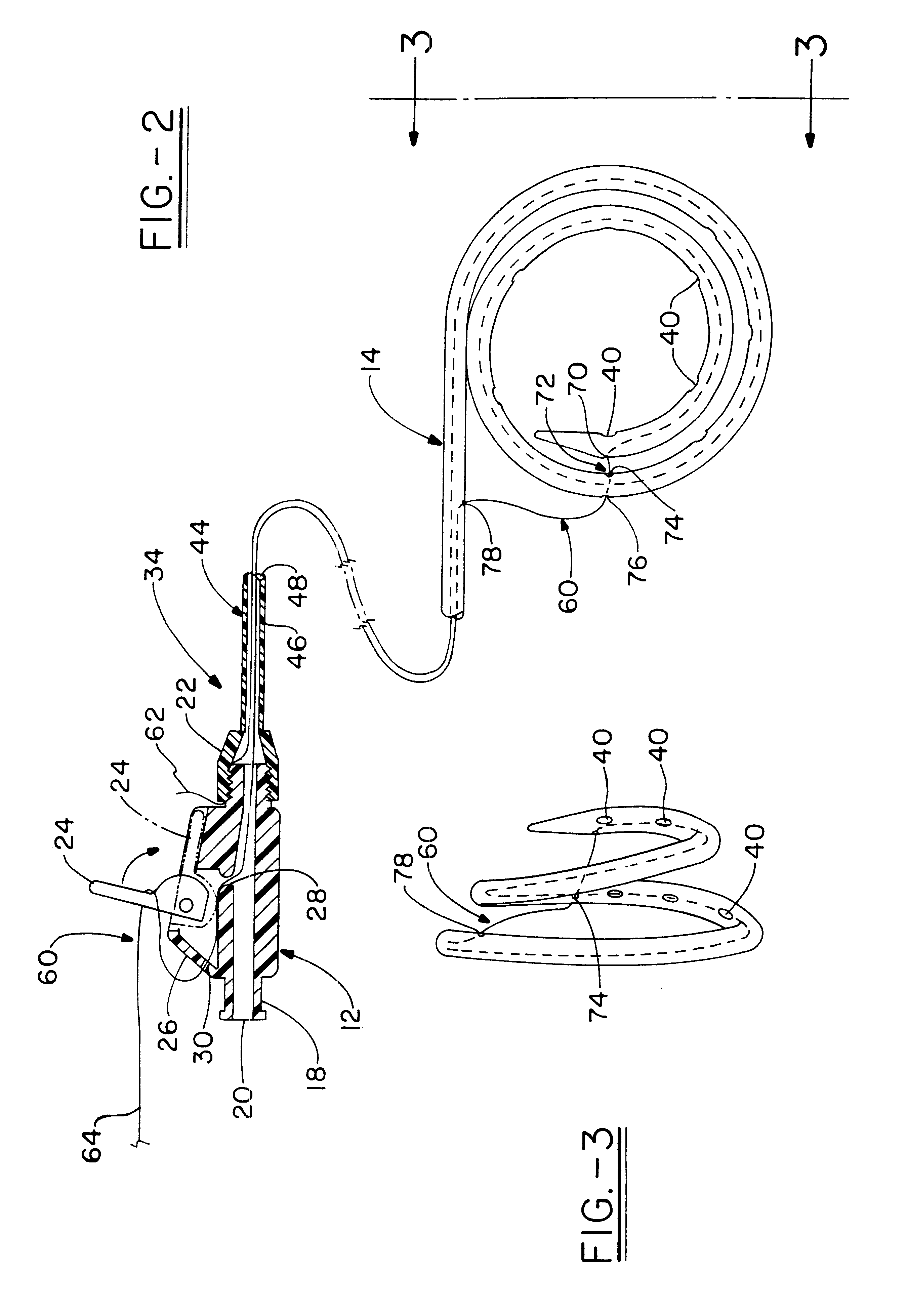
A multi-loop catheter for use with draining excess or infected fluid from a body cavity or for infusing medication into the body cavity, made in accordance with the concepts of the present invention, is indicated generally by the numeral 10 in the accompanying drawings, and is best seen generally in FIGS. 1 and 2. The primary components of the catheter 10 include a hub, generally indicated by the numeral 12, and an elongated hollow tubular member, generally indicated by the numeral 14. The hub 12 is typically made of a plastic semi-rigid material, while the tubular member is made of a flexible polymeric material, such as Ultrathane.TM.. Those skilled in the art will appreciate that the materials selected for the hub and the tubular member comply with the necessary regulations for medical devices.

The hub 12 includes a body 16 that has a coupling end 18, through which extends a channel 20. The coupling end 18 is usually connected or installed to another device upon insertion of the ca...


PUM


Abstract

A catheter(10) includes an elongated tubular member (14) having a proximal end (34) opposite a distal end (36). The distal end has a loop hole (70), at least one transition hole (72), and an end hole (78). A thread (60) has one end (62) fixed at the proximal end. The thread extends through the interior of the tubular member and out from the loop hole. The thread then extends through the transition hole and re-enters the tubular member at the end hole (78). The thread has a pulling end (64) exiting the tubular member at the proximal end. Application of a pulling force on the pulling end causes the distal end to form a first loop from the loop hole to the transition hole and a second loop from the transition hole to the end hole. The tubular member has a plurality of drainage/infusion ports (40) between the distal end and the end hole. The ports are in a radial position substantially opposite the radial position of the loop hole. The catheter (10) further includes a hub (12) having a channel (20) therethrough. The hub is coupled to the tubular member and a pivotable locking member (24) is coupled to the hub. The locking member secures the thread to the hub after the thread is fully pulled. The number of loops formed can be increased by adding more transition holes.

Description

This invention relates to catheters for draining fluid from a body cavity or for infusing medication into a body cavity. Particularly, this invention relates to a drainage / infusion catheter which forms multiple loops within the cavity to preclude inadvertent withdrawal of the catheter.The use of catheters for draining excess or infected body fluids from a body cavity or for infusing medication into a body cavity is well known. One use of the catheter is to drain excess fluid. For example, the catheter can be used to drain urine from the kidney when there is an obstruction in the ureter. Another use of the catheter is to drain fluid from an infected collection. For example, the catheter can be used to drain pus from an abdominal abscess. Inserting a drainage catheter into a body cavity is done with the aid of an insertion tool, such as a stiffening cannula. Once in position, the flexible distal portion at the end of the catheter is altered to essentially maintain the flexible distal ...

Claims


Application Information

Patent Timeline
IPC IPC(8): A61M25/00
CPCA61M25/0041A61M25/0097A61M2025/09125
Inventor MODY, MALAY K.
Owner MODY MALAY K DR
Why Eureka
Try Eureka