Mass sensor and mass sensing method

a mass sensor and mass technology, applied in the field of mass sensors, can solve the problems of unstable resonant frequency, time-consuming, and difficult detection of microorganisms based on their quantity

Inactive Publication Date: 2002-10-01
NGK INSULATORS LTD
View PDF4 Cites 83 Cited by
  • Summary
  • Abstract
  • Description
  • Claims
  • Application Information

AI Technical Summary

Problems solved by technology

However, with methods such as smeartest, staining, and microscopy, the detection of microorganisms is often difficult depending on their quantities, and time-consuming treatment such as the culture of specimens on an agar is required at need.
Also in the virus serological test, since measurements must be performed as a rule during both the acute stage and the convalescent stage for determination from the movement of the quantities of antibodies, there is the problem of time consuming from the point of view of prompt diagnosis.
However, such a mass sensor 80 has a problem in that since the part on which an external substance adheres and the part for detecting resonant frequency are in the same location, for example, the resonant frequency is unstable when the piezoelectric properties of the mass sensor 80 itself vary due to the temperature of the specimen or change in temperature.
However, such a mass sensor 30 has a problem of difference in sensitivity depending on whether the location where the mass of the diaphragm 31 changed is, for example, the central portion or the end portion of the diaphragm 31, even the same amount of change, and improvement for minimizing the difference in sensitivity is demanded.

Method used


Image

  • Mass sensor and mass sensing method
  • Mass sensor and mass sensing method
  • Mass sensor and mass sensing method

Examples


Embodiment Construction

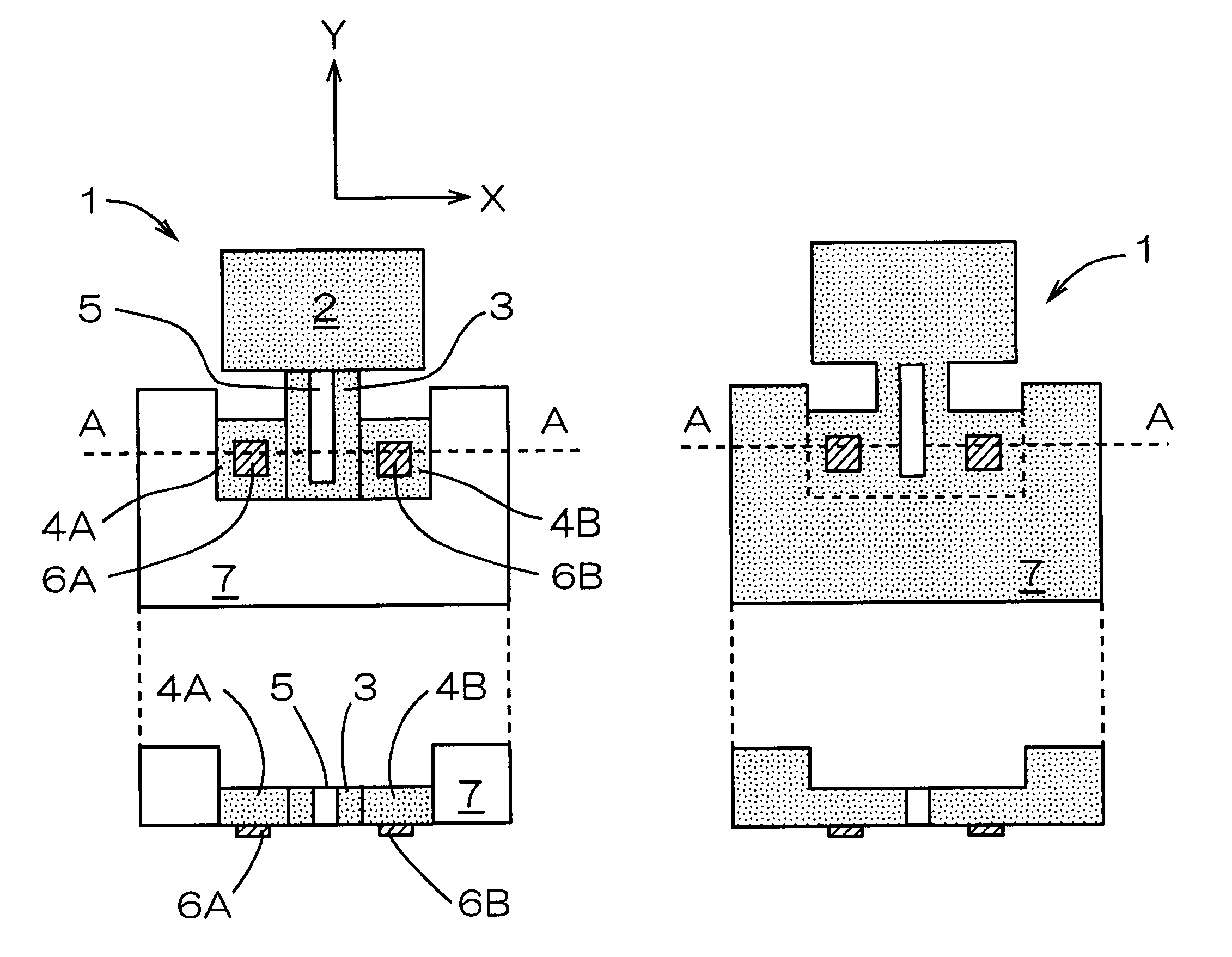
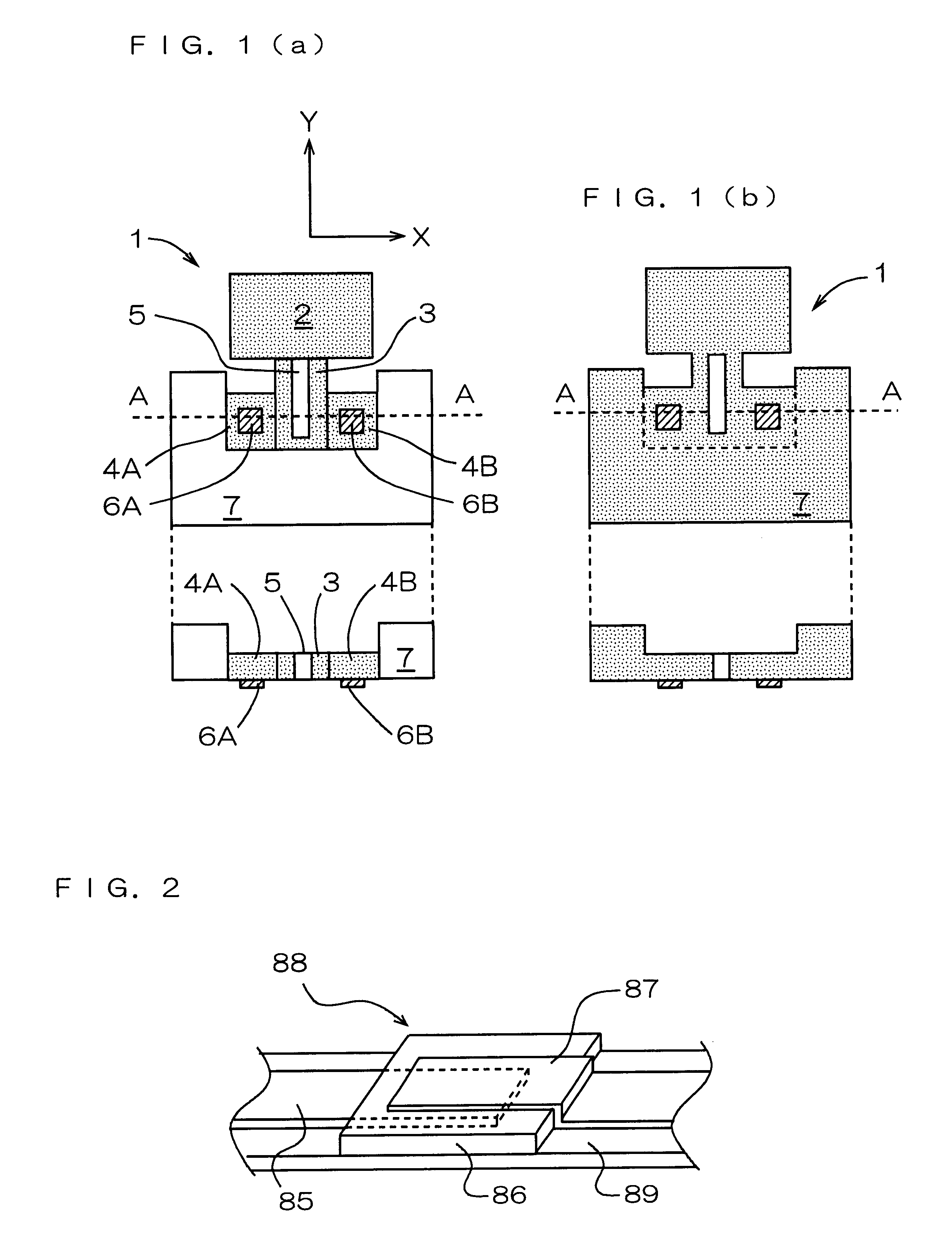
Since the mass sensor of the present invention has a structure in which difference in sensitivity depending on the location of change in the mass of the diaphragm, and the diaphragm easily oscillates at larger amplitudes, change in the micro mass can be known surely in a short time with a great accuracy from the specific value of change in the resonant frequencies of the resonating portion. Therefore, the mass sensor can be used favorably for sensing, for example, microorganisms or chemical substances, etc. in a specimen. The embodiments of the present invention will be described below with reference to drawings, focussing on a mass sensor comprising a catching substance reacting with and catching only a specific substance to be sensed, applied to a diaphragm, and on the use of that mass sensor.

As described above and as will be described below, the mass sensor of the present invention has many applications other than the measurement of change in the mass. Therefore, the present inve...


PUM

PropertyMeasurementUnit
massaaaaaaaaaa
thicknessaaaaaaaaaa
thicknessaaaaaaaaaa

Abstract

A mass sensor including: a connecting plate having one or more slit(s) and/or opening portion(s) formed therein and/or having a thin-walled portion and a thick-walled portion formed therein; a diaphragm joined with the connecting plate at respective side surfaces; a piezoelectric element; a sensing plate with the piezoelectric element being provided at least at one part on at least one surface of the sensing plate, which has its side surface joined with a side surface of the connecting plate in the direction perpendicular to the joining direction of the diaphragm and the connecting plate; and a sensor substrate with which at least a part of side surfaces of the connecting plate as well as the sensing plate are joined, and the diaphragm, the connecting plate, the sensing plate, and the piezoelectric element form a resonating portion. The mass sensor can conveniently be used for determining the mass of a substance to be sensed by measuring changes in resonant frequencies caused by changes in the mass of the diaphragm on which a catching substance for catching a substance to be sensed by reacting only with the object of sensing is applied.

Description

BACKGROUND OF THE INVENTION AND RELATED ART STATEMENTThe present invention relates to a mass sensor for determining a minute mass of a nanogram (10.sup.-9 g) order, for example, a mass sensor for sensing microorganisms such as bacteria, viruses, and protozoa (immune sensor), and a mass sensor for sensing moisture, toxic substances, or specific chemical substances such as taste components (moisture meter, gas sensor, and taste sensor), and a method for sensing a mass. In particular, the present invention relates to a mass sensor conveniently used for determining the mass of a substance to be sensed by measuring change in resonant frequencies caused by change in the mass of a diaphragm on which a catching substance for catching a substance to be sensed by reacting only with the object to be sensed is applied, and a method for sensing a mass.Since the mass sensor of the present invention is not limited to the measurement of change in the mass of the catching substance applied on a diap...

Claims


Application Information

Patent Timeline
Patent Type & Authority Patents(United States)
IPC IPC(8): G01G3/13G01G3/00G01G3/16G01N5/02G01N33/543
CPCG01G3/13
Inventor TAKEUCHI, YUKIHISAOHNISHI, TAKAOKIMURA, KOJI
Owner NGK INSULATORS LTD
Why Eureka
Try Eureka