Method and device for closing a door of an aircraft

a technology for aircraft doors and aircraft, which is applied in the direction of construction fastening devices, transportation and packaging, fuselages, etc., can solve the problems of reversing the latch action, the danger of the passenger door opening, so as to avoid additional production costs, increase the door weight, and facilitate the operation.

Inactive Publication Date: 2002-10-01
AIRBUS HELICOPTERS DEUT GMBH
View PDF9 Cites 22 Cited by
  • Summary
  • Abstract
  • Description
  • Claims
  • Application Information

AI Technical Summary

Benefits of technology

to provide an economical door latching and locking mechanism useful for any door but particularly suitable for various types of aircraft doors;
In the case of an existing latch mechanism, the latch drive is guided according to the invention along a remaining travel distance by means of a single drive for the latching and the locking, with a delayed movement of the safety locking mechanism into a safety locking position with a slightly spaced apart engagement with a lock element on the latch axis. The delayed movement is transferred to the lock element or elements from the single drive through a second force transmission coupling, with the latch drive or first force transmission coupling remaining in the latching position. The single drive and first and second couplings or force transmissions comprise for example a gear arrangement. Preferred, however are coupling rods and journal links. Gear wheels, cam disks or a cam controls are also suitable for realizing the first and second couplings. However, the use of rods and journal links with angular positions and dead points is particularly cost-effective. According to a special embodiment, these rods and links with angular positions and dead centers or points constitute the force transmission couplings between the single drive and the latching and safety locking mechanisms. An intermediate shaft can be arranged between the drive shaft and the lock drive or between the drive shaft and the latch drive. In this way, the movement mechanism can be optimized.
The invention provides the advantage that with only one drive, which already exists for the purpose of latching, the additional function of "safety locking" is achieved, whereby savings are achieved by avoiding additional production costs and additional door weight. There is no increase in inspection expenditure.
Although the latching and following safety locking involves an additional operator function at the door, the operator comfort achieved by a single drive is maintained, particularly since any direction reversal of the drive between latching and safety locking is avoided according to the invention.

Problems solved by technology

Dynamic loads on the door during the f light can result in vibrations which may cause a reversal of the latch action.
This can lead to the danger of the passenger door opening during flight.
Such a danger might also exist if the latch drive breaks.

Method used


Image

  • Method and device for closing a door of an aircraft
  • Method and device for closing a door of an aircraft
  • Method and device for closing a door of an aircraft

Examples


Embodiment Construction

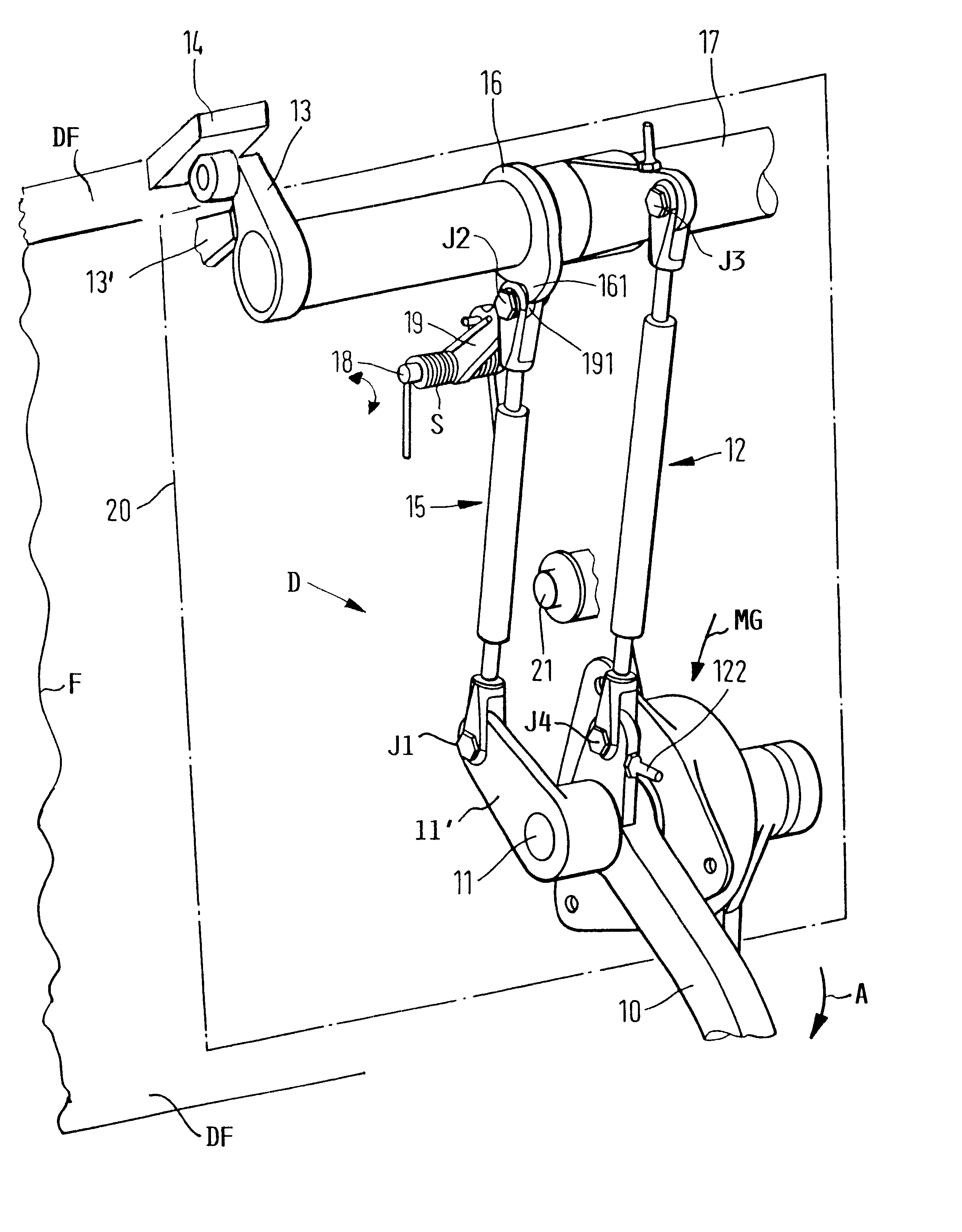
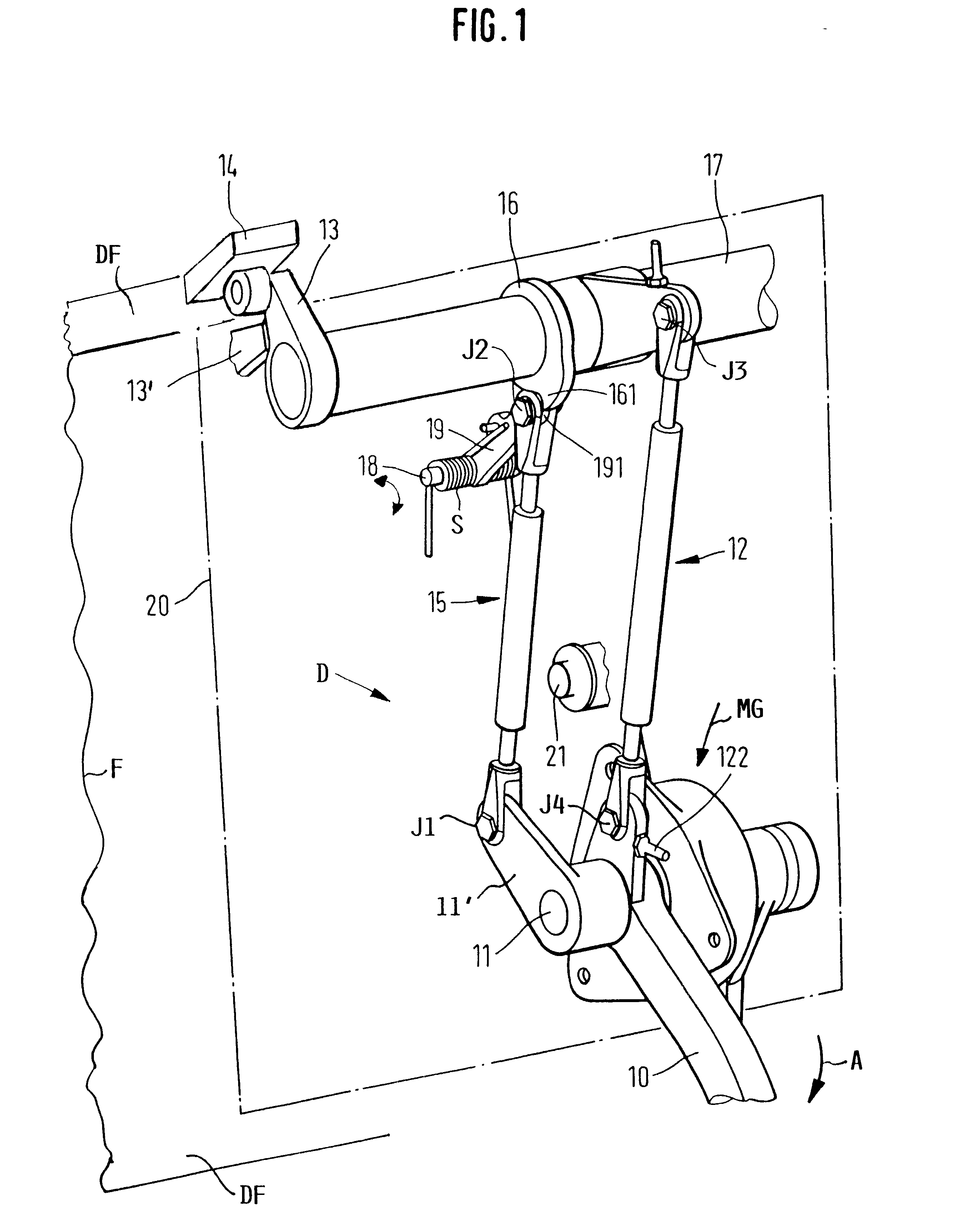
The passenger door 20, 200 as such is a construction which is known from DE 197 02 084 C1 mentioned above. The passenger door is hingeable by a support arm on one side of the door frame DF of the aircraft fuselage F, so as to be liftable, swingable, and lowerable.

The following description refers to FIG. 1 and explains the latching and locking functions achieved according to the invention by a movement mechanism or drive D. FIG. 1 shows the device according to the invention in a "latched and safety locked position".

During a closing operation of a passenger door or a freight door, for the sake of brevity, herein referred to as "door", an operator swings the door from an open position along a swinging in path. At the end of the swinging-in path, the door is positioned in front of a door opening formed by a door frame DF in the fuselage F. The operator in the interior of the passenger cabin operates the drive lever 10 of the drive D in the direction of the arrow A clockwise. The drive l...


PUM


Abstract

A door, especially an aircraft door, is first closed, for example manually. Then the door is first latched by a latching mechanism and locked by a locking mechanism. The latching mechanism and the locking mechanism are operatively connected through respective force transmitting couplings to a common drive in such a way that the latching mechanism is first moved to establish a latching position. Then, with a delay, the locking mechanism is moved into a locking position by the same drive to establish a latched and locked position.

Description

This application is based on and claims the priority under 35 U.S.C. .sctn.119 of German Patent Application 100 20 825.8, filed on Apr. 28, 2000, the entire disclosure of which is incorporated herein by reference.The invention relates to a method and a device for closing a door, particularly of an aircraft. When a door is closed in a closed position, it is then also brought into a latched position, whereby the door is latched in the frame of the fuselage structure by a latch mechanism.BACKGROUND INFORMATIONConventional aircraft doors have at least one latch mechanism with a drive shaft drivable by a latch drive. The drive shaft is connected to a latch element arranged on a latch axis or shaft and to the latch drive. The latch element is adapted for engaging a latch stop arranged in the frame of the aircraft structure. German Patent Publication DE 197 02 084 C1 discloses such a door for an aircraft. The door is moved from an open position to a closed position and then to a latched po...

Claims


Application Information

Patent Timeline
Patent Type & Authority Patents(United States)
IPC IPC(8): B64C1/00B64C1/14E05B17/00E05C21/02
CPCB64C1/1407E05B17/0029E05B17/0025
Inventor ERBEN, HANNESHOHL, ALFREDTENDYRA, THOMAS
Owner AIRBUS HELICOPTERS DEUT GMBH
Why Eureka
Try Eureka