Dynamic trim of a marine propulsion system

Inactive Publication Date: 2002-10-01
BRP US
View PDF27 Cites 53 Cited by
  • Summary
  • Abstract
  • Description
  • Claims
  • Application Information

AI Technical Summary

Problems solved by technology

Nor do the current techniques always consider the differing utility modes that a watercraft may experience along with the fact that each utility mode may redefine what is optimum with regard to trim position.

Method used


Image

  • Dynamic trim of a marine propulsion system
  • Dynamic trim of a marine propulsion system
  • Dynamic trim of a marine propulsion system

Examples


Embodiment Construction

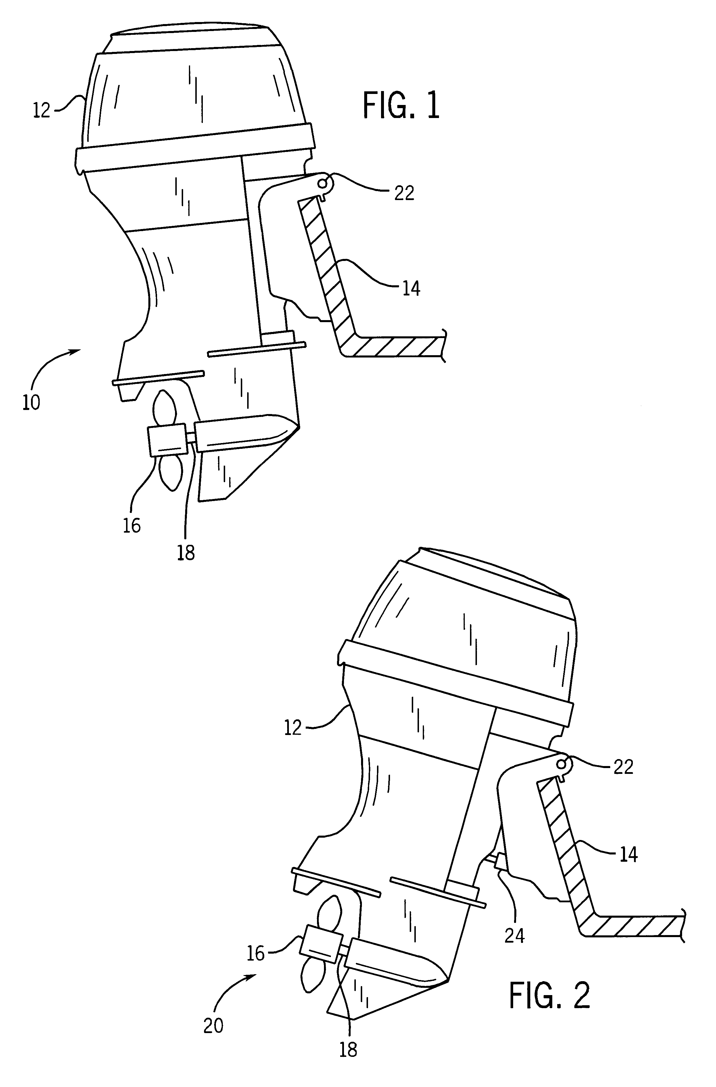
Turning now to the drawings and referring first to FIG. 1, a propulsion unit for a watercraft is shown in a first trim position 10. The propulsion unit is depicted as an outboard motor 12, but other propulsion devices are contemplated as being used in the presently disclosed technique. For example, the present technique is equally applicable to an inboard motor. The outboard motor 12 is attached to the transom 14 of a watercraft. The outboard motor 12 includes a prop 16 for producing thrust to motivate the watercraft through a body of water. The outboard motor 12 typically includes an internal combustion engine and power transmission components (none shown) coupled to the proper 16 by means of a shaft 18. The manner of producing and transmitting power to the prop is well known to those skilled in the art and is, therefore, not discussed in detail herein. It is noted that the outboard motor 12 is positioned such that the prop 16 is inward adjacent the transom 14 and is angled such th...


PUM


Abstract

A method and system for defining a program to control the trim position of a propulsion unit mounted on a watercraft for a desired utility mode. Also, a method and system for controlling the trim position in a given utility mode by using the defined program. In defining the program, a first utility mode is defined and the watercraft is operated in the defined mode as in normal operation. Multiple trim positions are selected throughout the course of operation in the defined mode. For each selected trim position, an operational parameter of the watercraft is sensed. Multiple values of the same parameter may be sensed and measured for a single trim position. After the parameters have been sensed for each trim position, a correlated data set is created. A correlated data set is saved to a memory device for each selected trim position of the defined utility mode. In controlling the trim position, the watercraft is again operated in the first utility mode. A current operational parameter is then measured. Having measured the current operational parameter, the correlated data sets are recalled from memory so that the current operational parameter may be compared with the stored parameters in the data sets. The trim position is then selected and set based on the comparison of the current parameter with those stored in the data set.

Description

1. Field of the InventionThe present invention relates generally to the field of propulsion systems for watercraft, such as fishing boats, ski boats, and other pleasure and utility craft. More specifically, the present invention relates to trim control of the propulsion unit in accordance with a defined utility of the watercraft.2. Description of the Related ArtRecreational watercraft are extremely popular for a variety of uses. Some of the more typical uses may include water skiing, other suitable towing activities, fishing, or simple pleasure riding. All of these activities require the ability of a propulsion system to move the watercraft through the water by providing an adequate amount of thrust.One conventional approach to providing thrust for a watercraft is the use of an internal combustion engine power source in an outboard or an inboard motor. The motor is typically mounted at the stem of the boat. An outboard motor is typically mounted to the transom of the boat and is dri...

Claims


Application Information

Patent Timeline
Patent Type & Authority Patents(United States)
IPC IPC(8): B63H20/10B63H20/00
CPCB63H20/10
Inventor KRUEGER, WILLIAM R.
Owner BRP US
Why Eureka
Try Eureka