Hard disk drive with slider support structure and head gimbal assembly

a technology of support structure and slider, which is applied in the direction of support for heads, instruments, record information storage, etc., can solve the problems of difficult reduction of load beam weigh

Inactive Publication Date: 2002-10-01
WESTERN DIGITAL TECH INC
View PDF10 Cites 85 Cited by
  • Summary
  • Abstract
  • Description
  • Claims
  • Application Information

AI Technical Summary

Benefits of technology

The invention has several advantages. Aperture 22 is provided under the lead pad 42, as shown in FIG. 5. Therefore, even if an adhesive agent bonding the slider 25 to the flexure tongue 20 protrudes from the joined portion, there is no possibility that the adhesive agent will contact the lead pads 41 to 44 and the bonding pads 28 to 31, because the adhesive agent will be moved downward from the aperture 22. For this reason, the lead pads 41 to 44 can be moved close to the bonding pads 28 to 31 without restrictions.

Problems solved by technology

Aperture 59h restricts the configuration of the point portion of the load beam 59 because it is formed in point portion, and makes a reduction in the weight of the load beam difficult.

Method used


Image

  • Hard disk drive with slider support structure and head gimbal assembly
  • Hard disk drive with slider support structure and head gimbal assembly
  • Hard disk drive with slider support structure and head gimbal assembly

Examples


Embodiment Construction

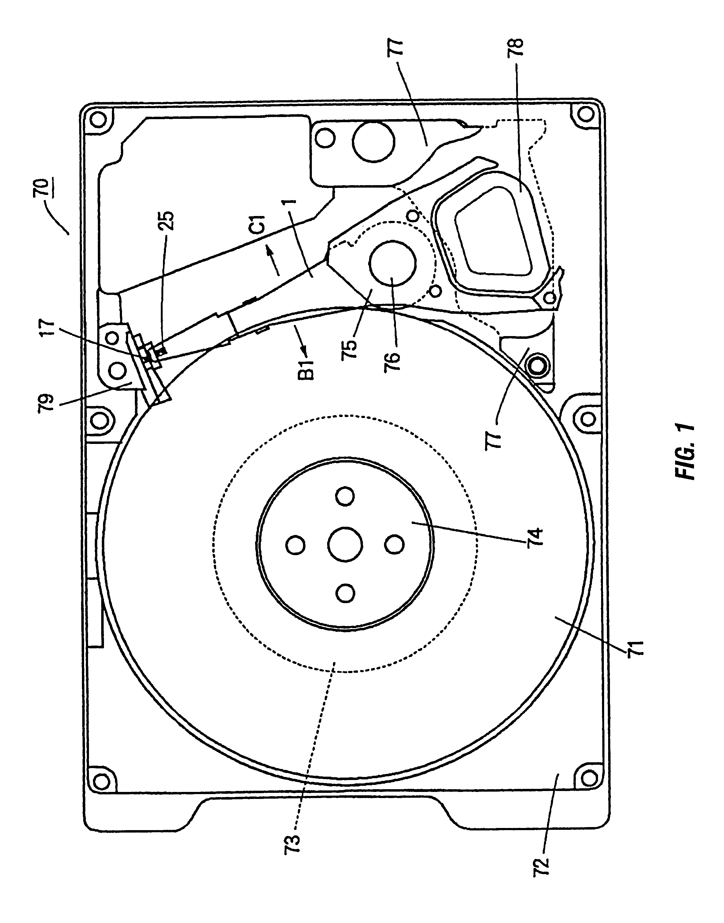
FIG. 1 is a top view of a hard disk drive 70 showing an embodiment of the present invention. In the figure, a disk 71 is supported integrally on the hub 74 of a spindle motor 73 mounted on a base 72 and is driven to rotate by the spindle motor 73. A HG assembly 1 to be described infra is formed integrally with a coil support portion 75 and freely rotatably supported by a rotating shaft 76 stood up in the base 72.

This coil support 75 holds a coil 78 at the opposite side from the HG assembly 1 with respect to the rotating shaft 76. This coil 78 constitutes a voice coil motor (hereinafter referred to as a VCM) along with a magnet (not shown) fixed above the coil 78 to an upper magnet holding plate 77 fixed to the base 72 and rotates the HG assembly 1 in the direction of arrow B1 or C1.

Note that in FIG. 1, the upper essential portion of the upper magnet holding plate 77 is cut out and shown for convenience, the external form being shown by a broken line. Also, a lower magnet holding pla...


PUM

PropertyMeasurementUnit
thicknessaaaaaaaaaa
thicknessaaaaaaaaaa
angleaaaaaaaaaa

Abstract

Apertures are formed in the portion of a flexure adjacent to the soldered portions between the bonding pads of the slider and the lead pads of lead end portions. With this, an adhesive agent for bonding the slider to a flexure tongue is moved downward from the apertures so there is no fear that the adhesive agent will contact the lead pads and the bonding pads. This design prevents the protrusion of an adhesive agent from short-circuiting the flexure, and absorbs a warp produced by shrinkage of a soldered portion by decreasing rigidity of the flexure. When both the bonding pad formed on the slider and the lead pad of a lead fixed to the platform of the flexure are disposed and soldered, the quality of the soldered portion is improved by locating the pads as close to each other as possible.

Description

1. Technical FieldThe present invention relates to a hard disk drive and a slider support structure having a head for moving the slider close to the disk recording surface of the hard disk drive, the construction of a head gimbal assembly, and a manufacturing method thereof. More particularly, the invention relates to the construction of a flexure for directly holding the slider, the construction of the pad of a point portion of a lead line, and a method of joining the slider pad and the lead pad.2. Description of the Related ArtThere are two prior art methods for joining a slider and a lead line: the bent lead method and the gold ball method. In the bent lead method of FIG. 11, the point portion of a lead 53 is pressed against a pad 63 formed on a slider 52 by the wedge 58 of a ultrasonic welder. Ultrasonic vibration is then applied to join these. elements. In the gold ball method of FIG. 12, the pad 63 of a slider 52 and the point portion of a lead 54 are orthogonally oriented rel...

Claims


Application Information

Patent Timeline
Patent Type & Authority Patents(United States)
IPC IPC(8): G11B5/48G11B21/02G11B21/21
CPCG11B5/4826G11B5/4853G11B21/02
Inventor TSUCHIYA, TATSUMIYOSHIDA, TATSUSHITSUCHIDA, HIROYASUINOUE, HIROOPATTANAIK, SURYAISHIKAWA, HIROMINANBA, MASAAKI
Owner WESTERN DIGITAL TECH INC
Why Eureka
Try Eureka