Thermal chimney for a computer

a computer and chimney technology, applied in the direction of lighting and heating apparatus, electrical apparatus casings/cabinets/drawers, instruments, etc., can solve the problems of unrecoverable disabling of the system, loud fans, and potential damage to the components

Inactive Publication Date: 2002-10-01
APPLE INC
View PDF11 Cites 92 Cited by
  • Summary
  • Abstract
  • Description
  • Claims
  • Application Information

AI Technical Summary

Problems solved by technology

It is also well known that when excessive heat occurs inside a computer system, there is a potential for damage to the components and possibly even irrecoverable disabling of the system.
Fans are loud and are distracting to the computer

Method used


Image

  • Thermal chimney for a computer
  • Thermal chimney for a computer
  • Thermal chimney for a computer

Examples


Embodiment Construction

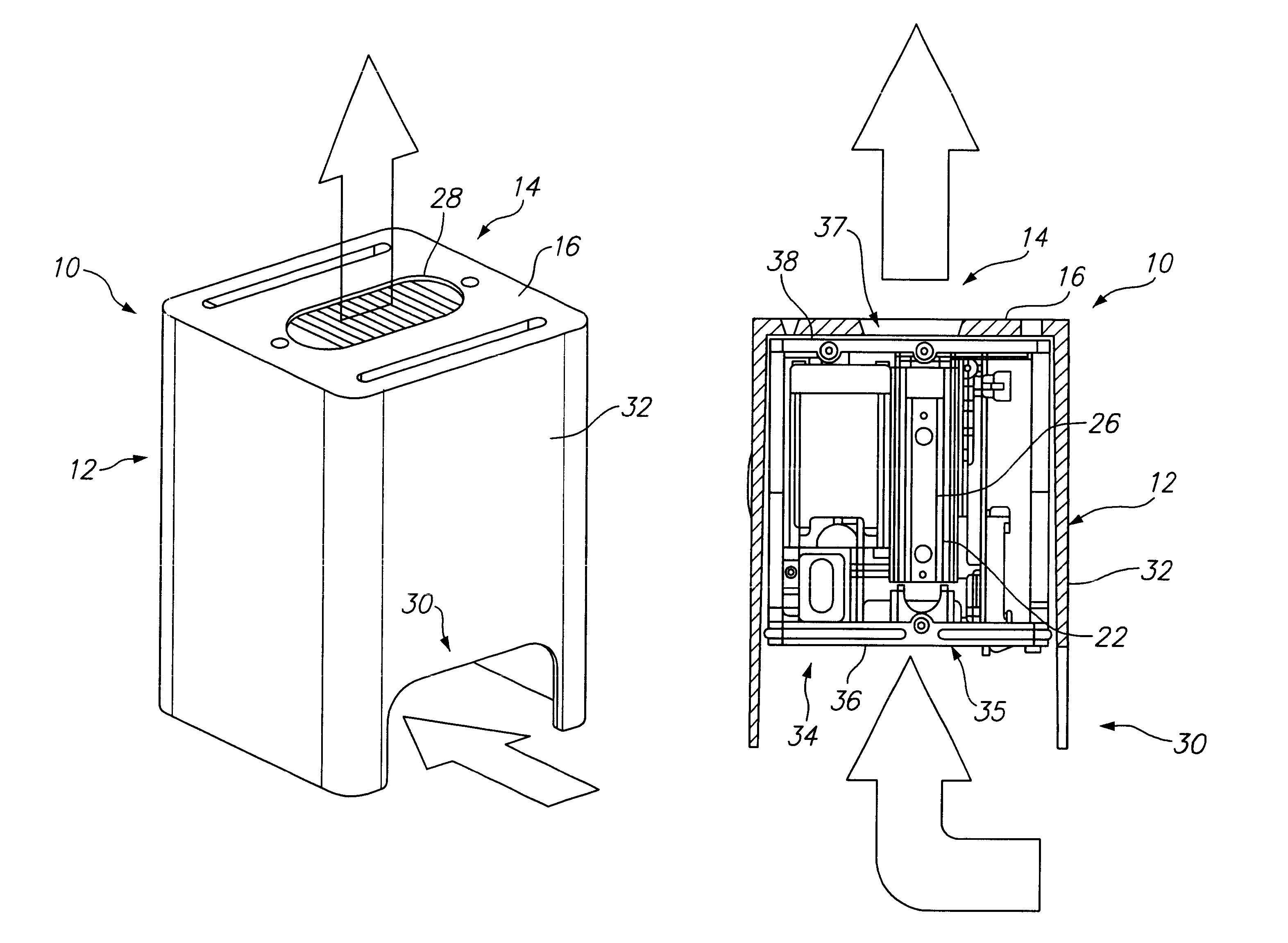
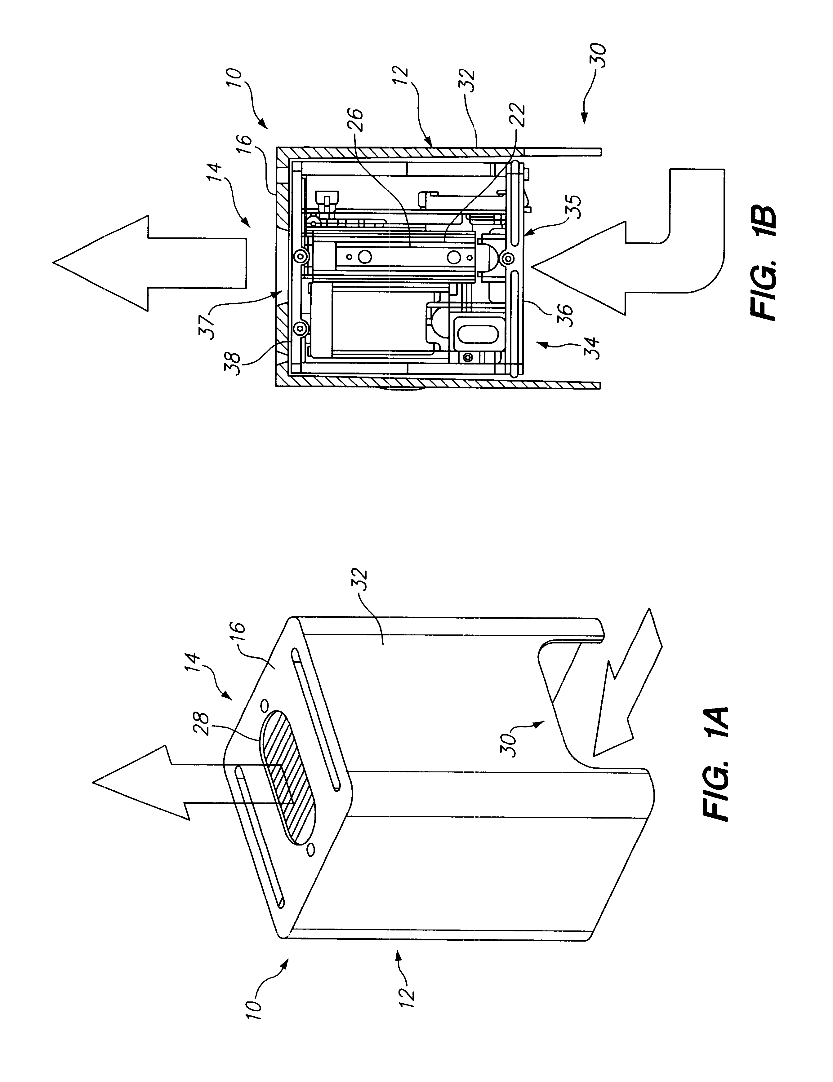
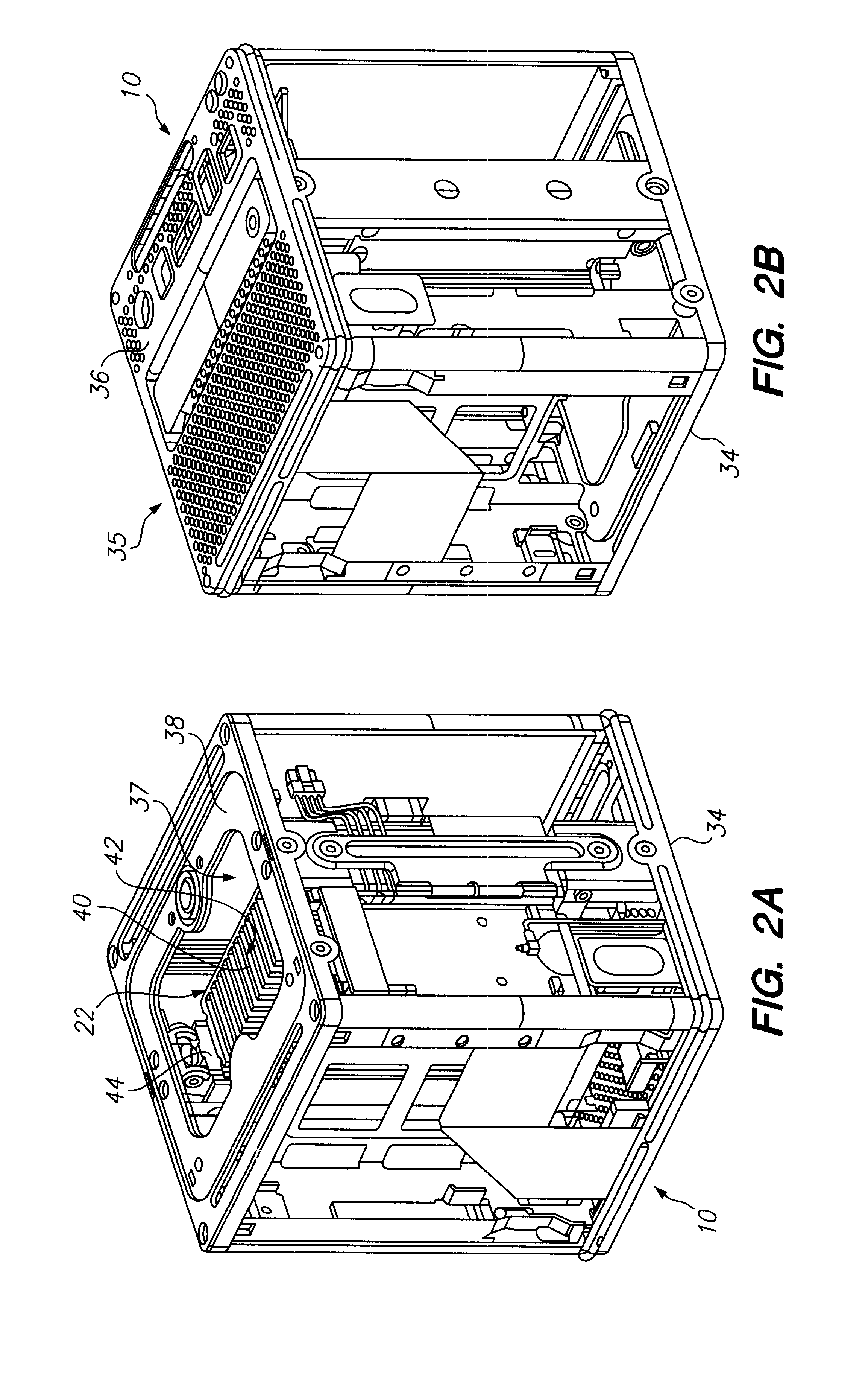
Referring to FIGS. 1A and IB, a computer C including the heat removal system 10 of the present invention comprises a casing 12 having an opening 14 in an exterior surface 16 thereof. Additionally, the computer C preferably includes a hard drive 18, a microprocessor 20, a heat sink 22, and a spreader plate 24. The heat sink 22 is preferably arranged between the hard drive 18 and the microprocessor 22 for maximum effectiveness and is aligned with the opening 14 in the casing 12 so as to form a thermal chimney 26. The spreader plate 24 is disposed between the microprocessor 20 and the heat sink 22 so as to conduct heat from the microprocessor 20 to the heat sink 22. The hard drive 18 is preferably connected directly to the heat sink 22.

As the computer system operates, the microprocessor 20 and the hard drive 18 generate heat. Heat is transferred from the microprocessor 20 to the heat sink 22, by conduction, through the spreader plate 24. Heat is also directly transferred by conduction ...


PUM


Abstract

A heat removal system for a computer comprising a casing enclosing a hard drive and a microprocessor, the casing including an opening in an exterior surface thereof; a heat sink positioned between the hard drive and the microprocessor, the heat sink being aligned with the opening in the casing so as to form a thermal chimney; and a spreader plate disposed between the microprocessor and the heat sink, the spreader plate conducting heat from the microprocessor to the heat sink.

Description

BACKGROUND OF THE INVENTION1. Field of the InventionThe present invention relates generally to a heat removal system for computer systems, and more specifically, to a heat removal system using a heat sink and a thermal chimney.2. Brief Description of the Related ArtIt is generally an accepted principle that computer systems generate heat during operation. It is also well known that when excessive heat occurs inside a computer system, there is a potential for damage to the components and possibly even irrecoverable disabling of the system. Accordingly, it is desirable to provide a method of removing heat from a computer system and one of the most common methods which has been used is a fan which forces air across hot components and directs the heated air out of the computer system.Forced air convection systems, such as those using fans, have several disadvantages. Fans are loud and are distracting to the computer user. Fans also take up valuable space in computer systems and must be ...

Claims


Application Information

Patent Timeline
IPC IPC(8): G06F1/20H05K7/20
CPCG06F1/20H05K7/20009
Inventor HOLMES, STEVEMILLER, WAYNEUPADHYA, GIRISHSMITH, RICHARD
Owner APPLE INC
Why Eureka
Try Eureka