Method and apparatus for putting articles into a queue

a technology for putting articles and queues, applied in the direction of conveyors, control devices of conveyors, storage devices, etc., can solve the problems of loss of energy, damage to fragile objects, and general bulky apparatus

Inactive Publication Date: 2002-10-15
CYBERNETIX
View PDF10 Cites 37 Cited by
  • Summary
  • Abstract
  • Description
  • Claims
  • Application Information

AI Technical Summary

Benefits of technology

By means of this system, when a plurality of articles are presented side by side (broadside-on) at the outlet from the inlet conveyor, said individualized article selected from said plurality of articles is detached (separated) from said plurality on being transferred by the multibelt conveyor to the outlet conveyor so that it is presented at the inlet of the outlet conveyor before any other article in said plurality; a second article in said plurality is then selected and the belts are then controlled to move differentially in a manner that is adapted to the position and to the outline of said second selected article, as determined from the image of the transverse profile of the group of articles remaining on said first conveyor, thus enabling the second article to be separated from the plurality of articles present on the inlet conveyor in the same manner as the first selected article was separated therefrom.
determining the number of articles in the group and the outline of each article by computation on the basis of the image, thereby making it possible to determine the position and the width of the base of each of the articles in a transverse vertical plane; and
The method and the apparatus of the invention make it possible to avoid dropping articles and to avoid recycling them.
Furthermore, the use of a multibelt conveyor makes it easier to transfer articles that are deformable (such as newspapers) and to transfer articles that might roll, in particular articles that are approximately cylindrical or spherical in shape, by giving them a conveyor path that is determined and controlled and in longitudinal translation without the article being turned or pivoted, unlike the pusher robot.

Problems solved by technology

Those apparatuses suffer from the drawback of causing the articles to drop on being transferred from one conveyor to another, and that can damage fragile articles; furthermore, the apparatus is generally bulky, because of the presence of deflectors and also the presence of return conveyors (recycling conveyors) which convey articles that have been separated out from the stream of articles treated by the apparatus to take them from the downstream end thereof back towards the upstream end; this gives rise to a loss of energy and also to the recycled articles being subjected to additional impacts on being delivered by the return conveyor back to the inlet to the apparatus.

Method used


Image

  • Method and apparatus for putting articles into a queue
  • Method and apparatus for putting articles into a queue
  • Method and apparatus for putting articles into a queue

Examples


first embodiment

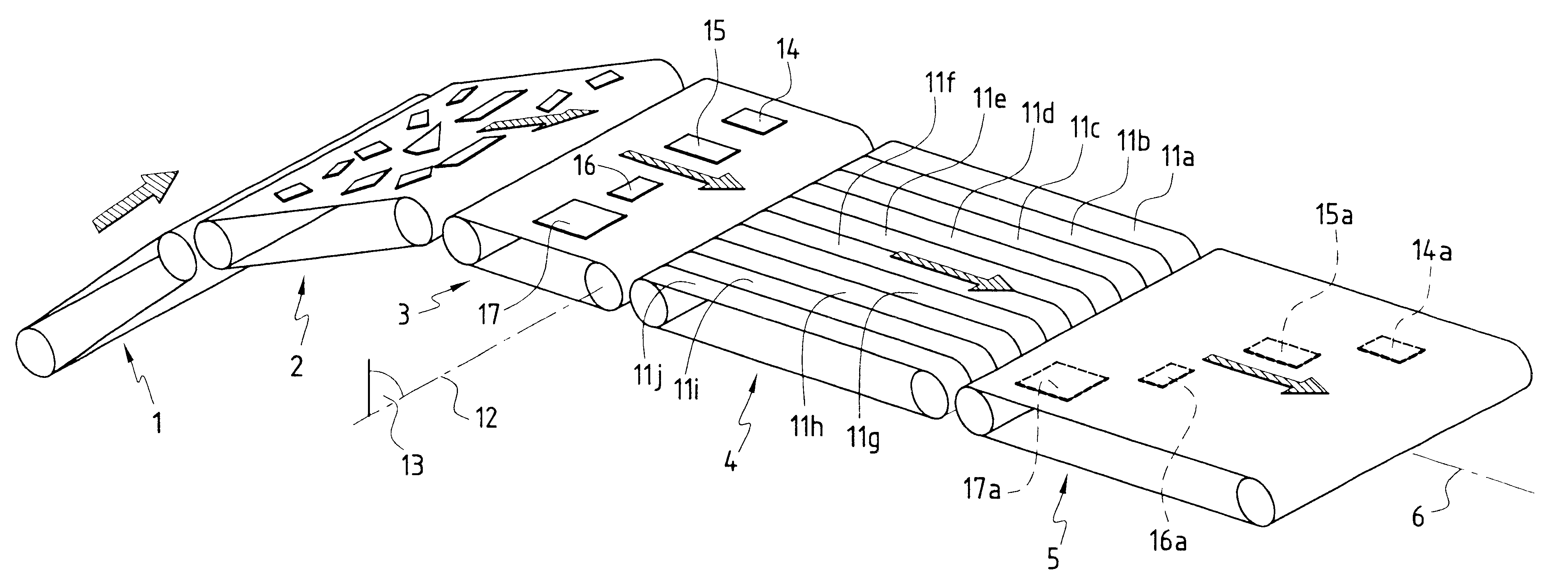
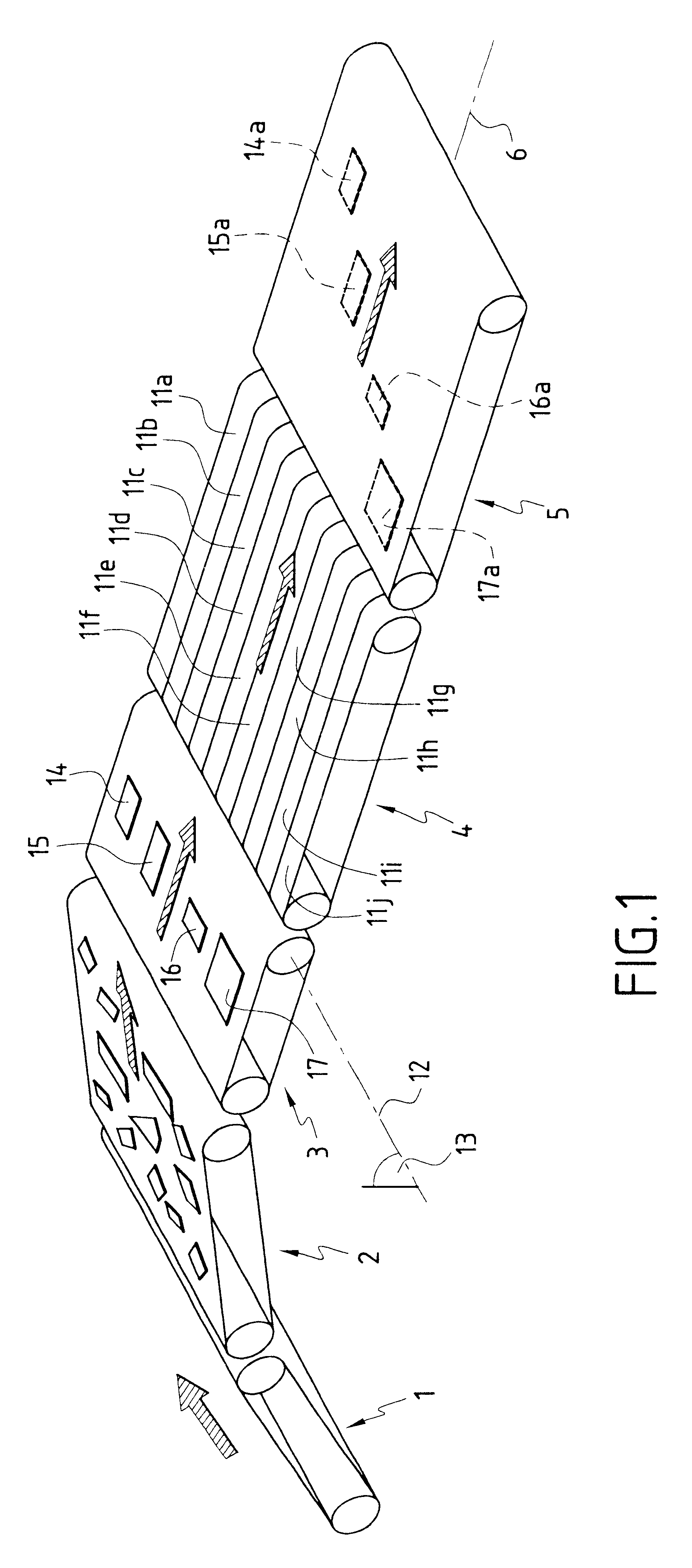
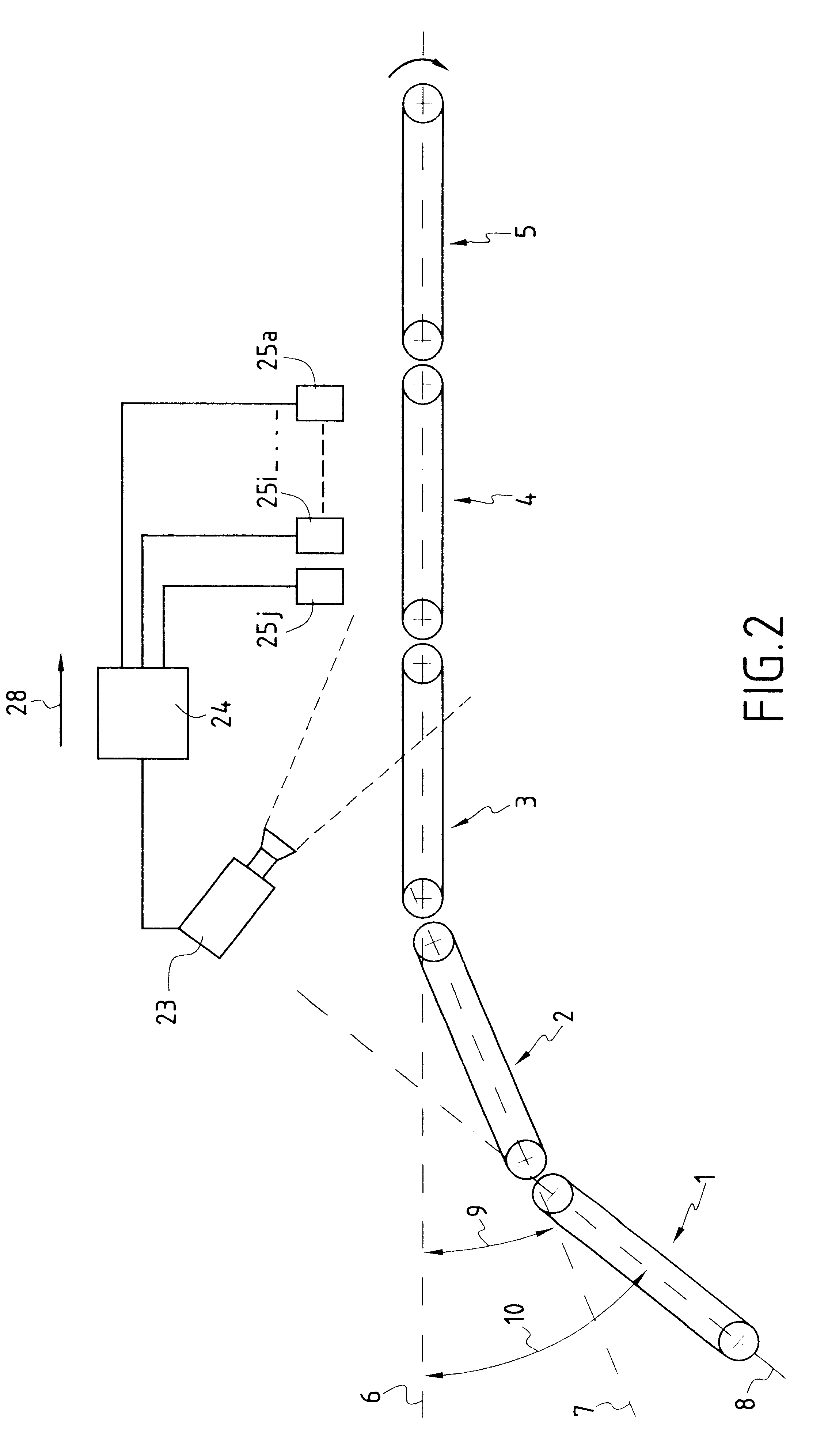
the multibelt conveyor as shown in FIGS. 3 and 4 is particularly intended for operating under the control of the unit 24 to drive the belts 11a to 11j selectively in on / off mode in application of the following sequence:

driving two adjacent belts 11a and 11b extending in line with the base 14, of article 14 at a speed 28 until it is detected that the article 14 has passed onto the following conveyor (referenced 5), while the other belts 11c to 11j are kept stationary; and then

driving the belt 11d to transfer the article 15 at the speed 28 while the belts 11a and 11b continue to be driven and the belts 11c and 11e to 11j remain stationary; then after the article 15 has passed onto the following conveyor (referenced 5):

driving the belt 11f to transfer the article 16 at the speed 28 with the belts 11a, 11b, and 11d continuing to be driven while the belts 11c, 11e, and 11g to 11j remain stationary; and then after the article 16 has passed onto the following conveyor (referenced 5):

drivin...


PUM


Abstract

The present invention relates to a method of putting articles into a queue and apparatus enabling he method to be implemented. According to the invention, apparatus for putting articles into a queue comprises a plurality of parallel transfer conveyors which are suitable, together or separately, for transferring an article from the outlet of an inlet conveyor to the inlet of an outlet conveyor, between which and in line with which the transfer conveyors extend, and which includes a camera for observing articles on the inlet conveyor and a device for deriving article outline and identity data from images taken by the camera, and a device for selectively actuating the transfer conveyors as a function of the outline and identity data.

Description

The present invention relates to a method of putting articles into a queue and to apparatus enabling the method to be implemented.The invention applies particularly to separating parcels in bulk, e.g. postal parcels, so as to form a queue of parcels disposed sequentially (i.e. one behind another).U.S. Pat. Nos. 5,918,723 and 5,950,800 in particular disclose apparatus for "singulating" articles (i.e. putting them into a queue) in which the apparatus is essentially constituted by a plurality of conveyors extending perpendicularly relative to one another, and generally driven at increasing speeds going from an inlet towards and outlet of the apparatus, which conveyors are associated with ramps and / or static deflectors for guiding the articles.Those apparatuses suffer from the drawback of causing the articles to drop on being transferred from one conveyor to another, and that can damage fragile articles; furthermore, the apparatus is generally bulky, because of the presence of deflector...

Claims


Application Information

Patent Timeline
Patent Type & Authority Patents(United States)
IPC IPC(8): B65G47/31B65G47/68
CPCB65G47/31B65G47/682
Inventor HERUBEL, PATRICKPICHON, JEAN-LOUISPALUMBO, CHARLES
Owner CYBERNETIX
Why Eureka
Try Eureka