Axial fan wheel

a technology of axial fan and axial fan hub, which is applied in the direction of machines/engines, liquid fuel engines, transportation and packaging, etc., can solve the problems of large centrifugal force in the fan hub, hinder the efficient operation, in terms of power, of the axial fan wheel, and achieve the effect of reducing the time of inertia, and rotating speed

Active Publication Date: 2018-04-26
MAN TRUCK & BUS AG
View PDF11 Cites 17 Cited by
  • Summary
  • Abstract
  • Description
  • Claims
  • Application Information

AI Technical Summary

Benefits of technology

[0013]The hub may be of lightweight construction, in particular between the inner ring and the outer periphery (for example the outer ring). Alternatively or additionally, it is possible for the inner ring to be situated outside a plane of rotation of the connection surfaces (for example outside a plane of rotation of the outer ring). For example, the hub may bulge or be curved in the direction of the drive shaft, at least at the inner ring as a connection point.
[0014]Conventional fan hubs for the fan drive are designed in such a way that the fan hub itself separates the negative-pressure side (or fan suction side) from the positive-pressure side (for example the engine compartment), whereby, due to a wall thickness of the fan hub that is formed for the purpose of the torque transmission, the moment of inertia of said hub is greater than in exemplary embodiments. If the moment of inertia of the fan hub were to be reduced by way of openings, the cooling power, at the same rotational speed, would become poorer, and, to build up the same pressure difference, the rotational speed would have to be increased. By contrast, exemplary embodiments having the element fastened in a rotationally fixed manner on the axial fan wheel are able to prevent air recirculation without significantly increasing the moment of inertia of the axial fan wheel or of the hub thereof. The same pressure difference can thus be generated at the same rotational speed with lower power consumption.
[0015]The at least one element may comprise an additional cover plate and / or an air guide device which counteracts the recirculation. The air guide device may comprise further rotor blades inside the periphery of the crown ring. The air guide element may be joined with the hub integrally in one piece (for example by forming the hub without additional mass) or screwed on as an additional sheet. The lightweight construction of the hub with the through-passages allows for example fuel reduction without recirculation of cooling air.

Problems solved by technology

This gives rise to correspondingly large centrifugal forces in the fan hub and, for the transmission of power and during changes in rotational speed, large shear forces.
However, a mechanism, integrated into the rotating fan hub, with moving parts, in particular with aperture discs which are displaceable in the direction of rotation with respect to the fan hub, hinders efficient operation, in terms of power, of the axial fan wheel.
The additional rotating mass of the mechanism leads to an increase in the power consumption of the axial fan wheel and thus for example in the fuel consumption.
Also, a mechanism integrated into the fan hub is subjected to the forces mentioned and, in the air stream, can jam due to dirt.
If the moment of inertia of the fan hub were to be reduced by way of openings, the cooling power, at the same rotational speed, would become poorer, and, to build up the same pressure difference, the rotational speed would have to be increased.

Method used


Image

  • Axial fan wheel
  • Axial fan wheel
  • Axial fan wheel

Examples


Embodiment Construction

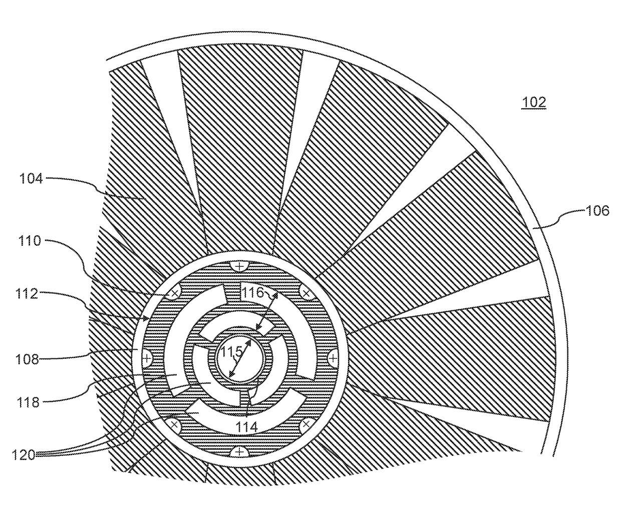
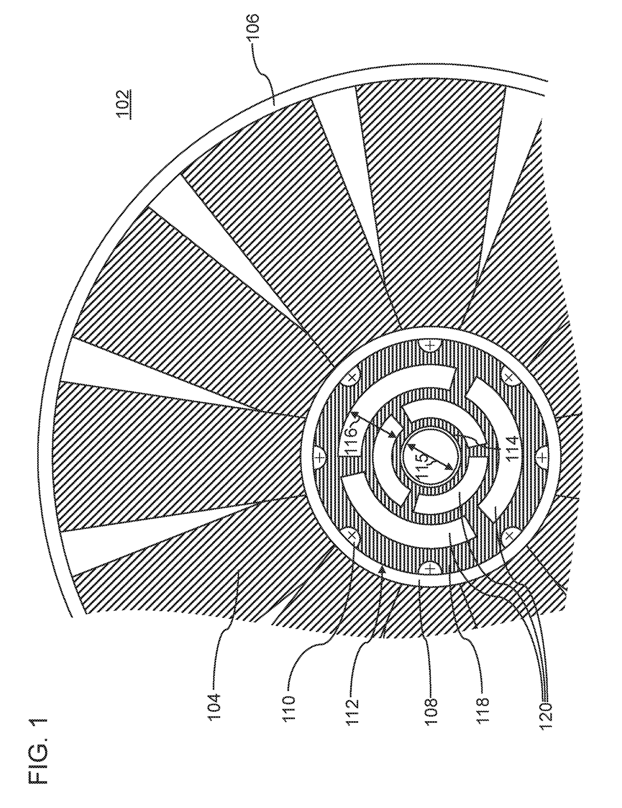
[0036]FIG. 1 shows a first exemplary embodiment of an axial fan wheel which is generally identified by the reference sign 102. The axial fan wheel comprises a multiplicity of rotor blades 104 which are bounded radially on the outside by a casing ring 106 and radially on the inside by a crown ring 108. On the crown ring 108, it is possible for crown webs 110 to project radially to the inside, with fastening points for the rotationally fixed connection (for example screwed connection) to a hub 112.

[0037]The hub 112 comprises an inner ring 114 which is connectable to a drive shaft, and connection surfaces on an outer periphery 118 of the hub 112, for example an outer ring or segments of such a ring. The hub 112 is connected to the crown ring 108 via the connection surfaces, for example via the outer ring.

[0038]For clarity of the description, it is assumed in the following description that the connection surfaces are formed along the outer periphery by an outer ring 118. Wherever the fo...


PUM


Abstract

An axial fan wheel, in particular for the radiator of a motor vehicle engine, is described. The axial fan wheel includes a crown ring having a multiplicity of rotor blades, a hub having an inner ring which is connected or connectable to a drive shaft, and having, for the purpose of torque transmission, connection surfaces along an outer periphery of the hub which are connected to the inner ring and to the crown ring. The hub has through-passages between the inner ring and the outer periphery. At least one element, arranged rotationally fixedly on the axial fan wheel inside the crown ring, is designed to maintain a pressure difference in the axial direction when the axial fan wheel rotates.

Description

BACKGROUND1. Technical Field[0001]The present disclosure relates to an axial fan wheel. In particular, an axial fan wheel for the radiator of a motor vehicle engine and a utility vehicle equipped therewith are described.1. Description of Related Art[0002]In order to supply ambient air to the radiator of a cooling circuit, an axial fan wheel for generating a negative pressure at the radiator is arranged for example downstream of the radiator in the flow direction. Depending on ambient-air temperature and cooling power, a fan hub of the axial fan wheel has to transmit considerable mechanical power to the rotor blades of the axial fan wheel, which power can be more than 10 kW in the utility vehicle sector. This gives rise to correspondingly large centrifugal forces in the fan hub and, for the transmission of power and during changes in rotational speed, large shear forces.[0003]Document EP 1 519 052 B1 describes an axial fan wheel whose hub end surface comprises a mechanism with displa...

Claims


Application Information

Patent Timeline
Patent Type & Authority Applications(United States)
IPC IPC(8): F04D29/32F04D29/58B60H1/00B60H1/32
CPCF04D29/329F04D29/5833B60H1/00035B60H1/3229F04D29/281F04D29/34F04D29/325F04D19/002F04D19/022F04D25/082
Inventor NEFF, ANDREASGELL, CHRISTIAN
Owner MAN TRUCK & BUS AG
Why Eureka
Try Eureka