Hydraulic circuit with a return line metering valve and method of operation

a technology of return line and metering valve, which is applied in the direction of fluid couplings, servomotors, couplings, etc., can solve the problems of loss of control of the cylinder and the machine member operated by the cylinder, potential danger, and failure to close the control metering valv

Inactive Publication Date: 2002-10-22
HUSCO INT INC
View PDF14 Cites 176 Cited by
  • Summary
  • Abstract
  • Description
  • Claims
  • Application Information

AI Technical Summary

Problems solved by technology

Electrically controlled metering valves have a potential problem of not closing when commanded because an obstruction across a metering element due to fluid contamination causes the solenoid armature to hang up.
Under that circumstance, control of the cylinder and of the machine member operated by the cylinder are lost.
This can create a potentially hazardous situation where an open valve allows fluid to drain from the cylinder causing the machine member to drop by gravity.
In this situation, energy in the exhausting fluid is being lost and additional power has to be consumed by the pump to provide the pressurized fluid for operating the arm and possibly other functions on the machine.
This limits the rate of those powered functions and corresponding slows work function cycle time.
Thus there is a degree of inefficiency to this operation.
A further concern in hydraulic systems is that some valves are sensitive to the pressure drop across their metering elements.
As a consequence, a small error in the control of the actuator current or a small change in the valve response can have a dramatic impact on the flow rate at higher pressure drops.
This can result in a significant difference in the movement of the machine member being controlled by the valve.

Method used


Image

  • Hydraulic circuit with a return line metering valve and method of operation
  • Hydraulic circuit with a return line metering valve and method of operation
  • Hydraulic circuit with a return line metering valve and method of operation

Examples


Embodiment Construction

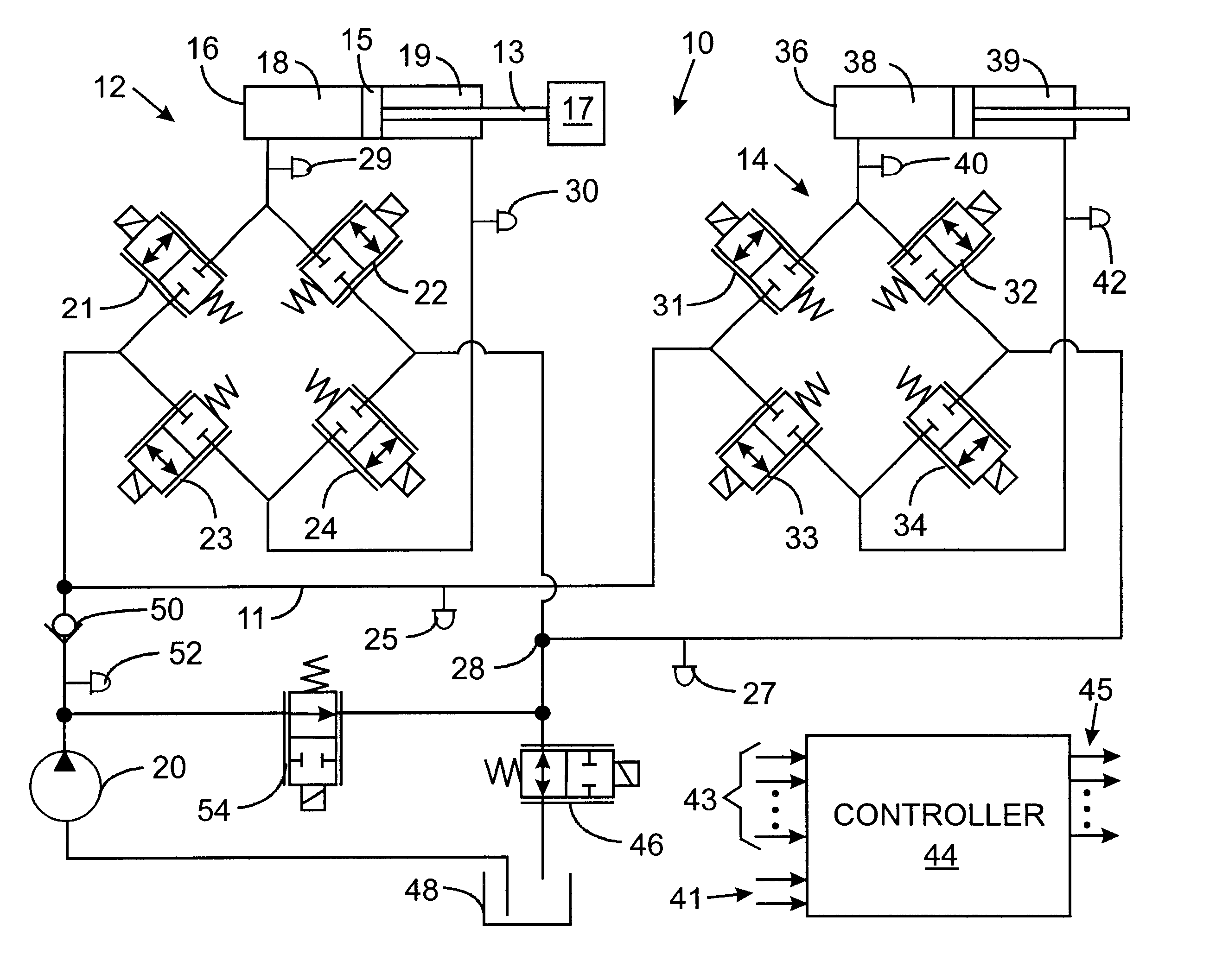
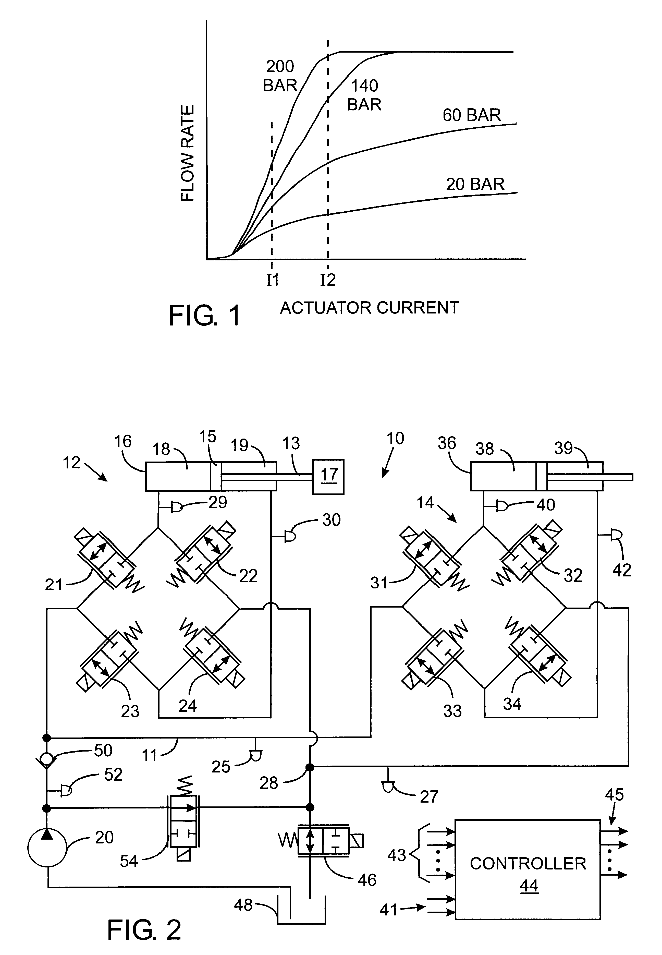
With reference to FIG. 2, a hydraulic system 10 controls two separate functions 12 and 14 on a machine which are supplied with pressurized fluid via a common supply line 11. It should be understood that additional functions also may be powered by this system. The first function 12 has a first hydraulic cylinder 16 containing a piston 15 that is connected by a rod 13 to drive a member on the machine, as represented by load 17. The piston divides the internal cavity of the cylinder 16 into a head chamber 18 and a rod chamber 19, both of which are connected to an array of four bidirectional, proportional control valves 21, 22, 23 and 24 that are electrically operated by solenoids. The first control valve 21 controls the flow of hydraulic fluid from a pump 20 to the head chamber 18. The second bidirectional, proportional control valve 22 regulates the flow of fluid between the head chamber 18 and a shared return line 28. Similarly, the third proportional control valve 23 governs the flo...


PUM


Abstract

A hydraulic system controls the flow of fluid to and from several functions on a machine. Each function has a valve assembly through which fluid is supplied under pressure from a source to an actuator and through which fluid returns from the actuator to a shared return line connected by a return line metering valve to the system tank. There are several regeneration modes of operation in which fluid exhausted from one port is supplied into the other port of the same actuator, which eliminates or reduces the amount of hydraulic fluid that must be supplied from the source. In some regeneration modes, input fluid for an actuator is obtained from another hydraulic function via the shared return line. In these regeneration modes an electronic controller operates the return line metering valve to restrict fluid from flowing into the tank from the shared return line, so that the fluid will be available to be supplied into an actuator port.

Description

Not ApplicableNot Applicable1. Field of the InventionThe present invention relates to hydraulic circuits that operate machinery; and more particularly to controlling the pressure and flow of hydraulic fluid supplied to power actuators of that machinery.2. Description of the Related ArtA wide variety of machines have working members that are driven by hydraulic cylinder and piston assemblies. Each cylinder is divided into two internal chambers by the piston and selective application of hydraulic fluid under pressure to either of the chambers moves the piston in a corresponding direction. While that action is occurring, fluid is being drained or exhausted, from the other,cylinder chamber to a tank for the hydraulic system.Traditionally the flow of hydraulic fluid to and from the cylinder was controlled by a manually operated valve, such as the one described in U.S. Pat. No. 5,579,642. There is a trend away from manually operated hydraulic valves toward electrically controlled solenoid...

Claims


Application Information

Patent Timeline
Patent Type & Authority Patents(United States)
IPC IPC(8): F15B11/00F15B11/044F15B11/16F15B11/02F15B21/14
CPCF15B11/006F15B11/044F15B11/16F15B2211/20538F15B2211/30575F15B2211/3111F15B2211/3144F15B2211/31588F15B2211/327F15B2211/353F15B2211/45F15B2211/6309F15B2211/6313F15B2211/6346F15B2211/6654F15B2211/71F15B2211/88
Inventor STEPHENSON, DWIGHT B.PFAFF, JOSEPH LAWRENCE
Owner HUSCO INT INC
Why Eureka
Try Eureka