Receiver-integrated condenser for a vehicle

a receiver-integrated, condenser technology, applied in the direction of subcoolers, light and heating equipment, transportation and packaging, etc., can solve the problems of the cap member of the bottom portion of the receiving unit not being able to be removed, and the condenser's mounting performance on the vehicle is deteriorated

Inactive Publication Date: 2002-10-29
DENSO CORP
View PDF5 Cites 43 Cited by
  • Summary
  • Abstract
  • Description
  • Claims
  • Application Information

AI Technical Summary

Problems solved by technology

However, in this case, the connection portion is disposed to protrude to a side of the receiving unit, and the mounting performance of the condenser on the vehicle is deteriorated.
In addition, because the refrigerant outlet portion of the super-cooling portion is provided at a direct lower side of the receiving unit, a cap member of a bottom portion of the receiving unit cannot be detachable.

Method used


Image

  • Receiver-integrated condenser for a vehicle
  • Receiver-integrated condenser for a vehicle
  • Receiver-integrated condenser for a vehicle

Examples


first embodiment

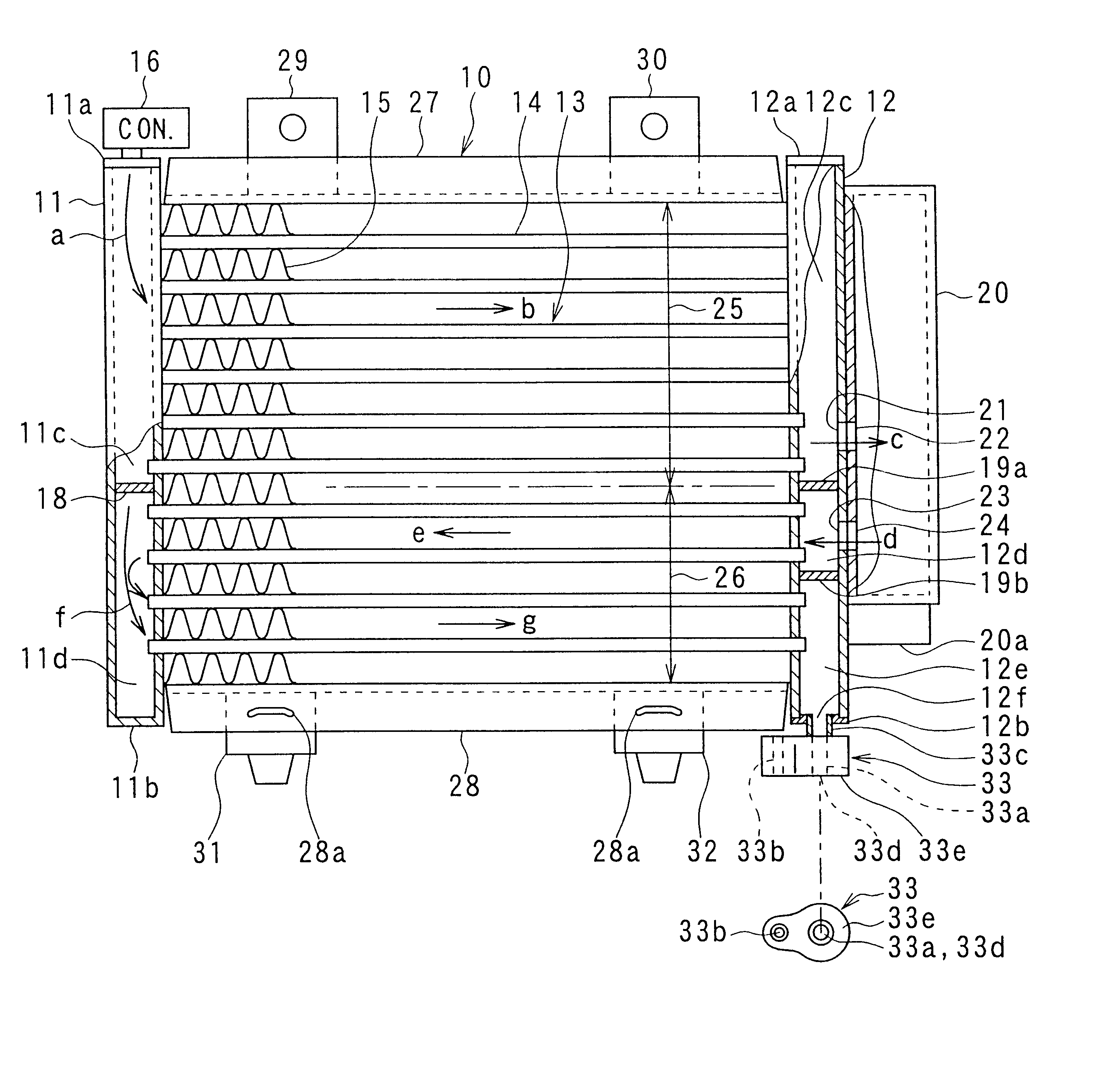
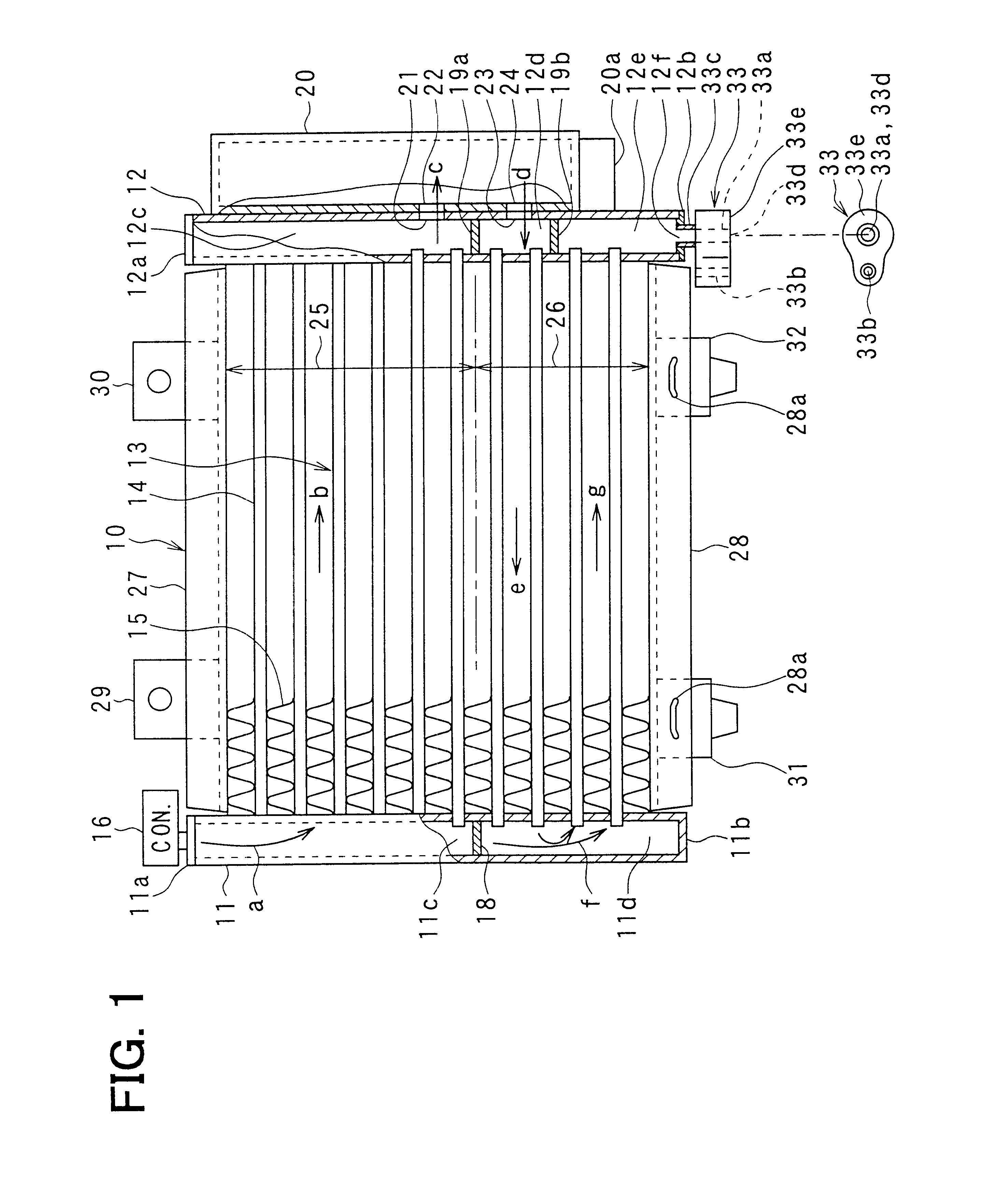
In the first embodiment, the receiver-integrated condenser 10 is a multi-flow type. The core portion 13 includes plural flat tubes 14 through which refrigerant flows in a horizontal direction, and plural corrugated fins 15 each of which is disposed between adjacent flat tubes 14. The flat tubes 14 are disposed in parallel with each other to be connected to both the first and second header tanks 11, 12. That is, one side end of each tube 14 is connected to the first header tank 11 to communicate with an interior of the first header tank 11, and the other side end of each tube 14 is connected to the second header tank 12 to communicate an interior of the second header tank 15.

A refrigerant inlet-side connector 16 is disposed to be connected to the upper side cap 11a of the first header tank 11. The refrigerant inlet-side connector 16 is for being connected to a refrigerant pipe 83 (see FIGS. 3, 4) at a refrigerant discharge side of a compressor 80.

In the first embodiment of the presen...

second embodiment

Because the connection surface 33e of the outlet connector 33 is toward the upper side, the connector 67 of the refrigerant pipe 66 is disposed on the connection surface 33e of the outlet connector 33. Therefore, by screwing the bolt 34 into the connectors 33, 67 from the upper side of both the connectors 33, 67, both the connectors 33, 67 can be readily connected. Even in the second embodiment, because the outlet connector 33 is disposed to be offset to a side (e.g., vehicle rear side) of the receiving unit 20 when being viewed from the upper side of the receiving unit 20, the cap member 20a can be detachably disposed.

In the second embodiment, the other parts are similar to those in the above-described first embodiment.

A third preferred embodiment of the present invention will be now described with reference to FIG. 6. In the third embodiment, a pipe member 280 defining a refrigerant passage is disposed at a position corresponding to the lower side plate 28 described in the first a...

third embodiment

Further, the elastic support members 31, 32 are disposed in the bottom surface portion of the pipe member 280 at both right and left positions. In the present invention, metal support pins 37 are bonded to the bottom surface portion of the pipe member 280, and are press-fitted into the elastic members 38. The elastic members 38 are made of an elastic material such as a rubber, and is formed into a cylindrical shape.

According to the third embodiment of the present invention, the pipe member 280 corresponding to the lower side plate 28 of the first embodiment is used as the refrigerant passage, the number of the tubes 14 can be reduced in the super-cooling portion 26. Therefore, the receiver-integrated condenser 10 can be manufactured in low cost.

Although the present invention has been fully described in connection with the preferred embodiments thereof with reference to the accompanying drawings, it is to be noted that various changes and modifications will become apparent to those s...


PUM


Abstract

In a core portion of the receiver-integrated condenser, a condensing portion is disposed at an upper side of a super-cooling portion. A receiving unit is disposed at one end side of the core portion in a width direction, and refrigerant is U-turned in a refrigerant passage of the super-cooling portion at the other end side of the core portion in the width direction. In addition, a refrigerant outlet of the super-cooling portion is provided at the one end side of the core portion, a connector connected to the refrigerant outlet is disposed at a direct lower side of the refrigerant outlet, and the connector has a bottom surface used as a connecting surface connected with a pipe connector of a refrigerant pipe.

Description

This application is related to Japanese Patent Application No. 2000-385562 filed on Dec. 19, 2000, the contents of which are hereby incorporated by reference.1. Field of the InventionThe present invention relates to a pipe connection structure of a receiver-integrated condenser in a refrigerant cycle system for a vehicle.2. Description of Related ArtIn a receiver-integrated condenser 110 arranged integrally with a radiator 161 in a vehicle, as shown in FIGS. 7A, 7B, a condensing portion 125 is disposed at an upper side in a core portion 113, and refrigerant after passing through the condensing portion 125 is introduced into a receiving unit 120 to be separated into gas refrigerant and liquid refrigerant. Further, liquid refrigerant within the receiving unit 120 flows through a super-cooling portion 126 disposed at a lower side in the core portion 110 to be super-cooled. In addition, a connector portion 140 used as a refrigerant outlet of the core portion 113 is positioned at one end...

Claims


Application Information

Patent Timeline
Patent Type & Authority Patents(United States)
IPC IPC(8): F25B39/04F25B40/02F25B40/00B60H1/00B60H1/32
CPCF25B39/04F25B40/02F25B2339/0441
Inventor SHIBATA, KAZUJIYOSHIDA, YOSHIO
Owner DENSO CORP
Why Eureka
Try Eureka